Air control valve and air control valve assembly

A technology of air control and inflation valve, applied in the direction of control valve and air release valve, pneumatic brake, brake, etc., which can solve the problem of short service life of the rubber diaphragm of the main seal, high requirements on flatness and surface roughness, and long stroke And other issues

Active Publication Date: 2017-05-17
CHINA SHENHUA ENERGY CO LTD +2
View PDF6 Cites 19 Cited by
  • Summary
  • Abstract
  • Description
  • Claims
  • Application Information

AI Technical Summary

Problems solved by technology

The spool valve integrates many functional holes, and is sealed with the copper material of the spool valve seat. It also has high requirements for flatness and surface roughness, and the metal grinding process is difficult, and the metal wear is large; The service life of the rubber diaphragm of the part is short, which makes the reliable period of the brake valve short; the air quality requirements are also high, and the operating environment of the railway freight car is often relatively harsh, which leads to the maintenance period of the control valve barely reaching 2 years
[0003] On the other hand, with the upgrading of railway vehicles, the 120-type control valve, as the main type of brake in the past, has gradually emerged the limitation that it cannot adapt to the requirements of various types of vehicles.

Method used


Image

  • Air control valve and air control valve assembly

Examples


Embodiment Construction

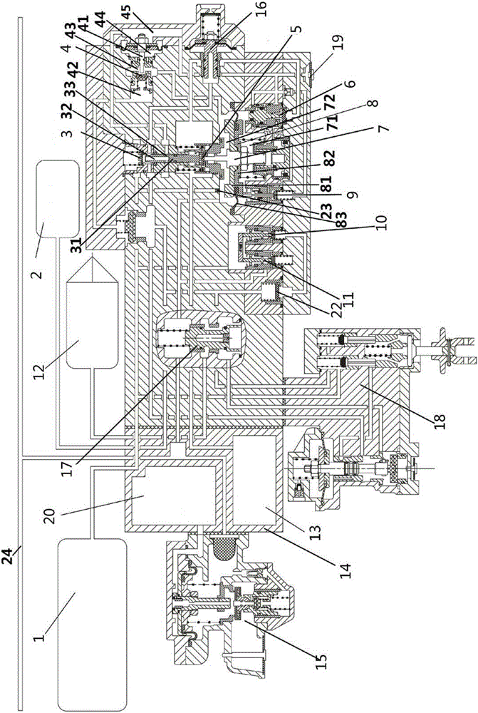
[0031] Specific embodiments of the present invention will be described in detail below in conjunction with the accompanying drawings. It should be understood that the specific embodiments described here are only used to illustrate and explain the present invention, and are not intended to limit the present invention.

[0032] In the present invention, in the case of no contrary description, the used orientation words such as "upper and lower" usually refer to the orientation or positional relationship based on the orientation or positional relationship shown in the drawings, and are only for the convenience of describing the technology and simplify the description, rather than indicating or implying that the device or element referred to must have a specific orientation / construct and operate in a specific orientation. "First and second" are used for descriptive purposes only, and do not have the actual numbering meaning.

[0033]Aiming at the poor lubrication performance of t...


PUM


Abstract

The invention relates to the field of train control, in particular to an air control valve and an air control valve assembly. The air control valve comprises a main piston valve, an auxiliary air cylinder inflation valve, an accelerated relieving air cylinder inflation valve, a partial relieving control valve and a brake valve, wherein the initial states of the auxiliary air cylinder inflation valve, the accelerated relieving air cylinder inflation valve, the partial decreasing control valve and the brake valve are all closed states; the main piston valve comprises a valve core assembly and a main valve spring; the valve core assembly comprises a main piston rod and a main piston; the main piston is installed in the middle of the main piston rod, and the lower portion of the main piston rod is sleeved with the main valve spring; a center cavity for accommodating the valve core assembly is divided into a driving chamber and a main valve spring chamber by the main piston; the driving chamber communicates with a train pipe, the main valve spring is arranged in the main valve spring chamber, and the main valve spring chamber communicates with an auxiliary air cylinder; the valve core assembly slides up and down in the center cavity under the air pressure of the driving chamber, the air pressure of the main valve spring chamber and the action of the main valve spring, the effects such as partial decreasing, braking, relieving and pressure maintaining are achieved, the pressure of a brake cylinder and the pressure of all air cylinders are controlled to be changed correspondingly; and finally, the air control valve and the air control valve assembly meet the application requirements of railway freight trains under different working conditions.

Description

technical field [0001] The invention relates to the field of train control, in particular to an air control valve and an air control valve assembly. Background technique [0002] There are nearly 800,000 railway freight cars in China. The main air brakes are all based on the 120-type control valve, and the main control mechanism is a slide valve template structure. The spool valve integrates many functional holes, and is sealed with the copper material of the spool valve seat. It also has high requirements for flatness and surface roughness, and the metal grinding process is difficult, and the metal wear is large; The service life of the rubber diaphragm is short, which makes the reliable cycle of the brake valve short; the air quality requirements are also high, and the operating environment of railway freight cars is often relatively harsh, which leads to the maintenance cycle of the control valve barely reaching 2 years. [0003] On the other hand, with the replacement o...

Claims


Application Information

Patent Timeline
Patent Type & Authority Applications(China)
IPC IPC(8): B60T15/02B61H11/06
CPCB60T15/021B61H11/06
Inventor 康凤伟肖德富辛民庄德重李春林张恒谢磊李科明安鸿
Owner CHINA SHENHUA ENERGY CO LTD
Why Eureka
Try Eureka