
High-rotating-speed starting clutch based on internal engagement of bevel gear

A bevel gear and internal meshing technology, applied in the field of high-speed inspired clutch structure, can solve the problems of unable to start the car, complicated control, flameout, etc., and achieve the effects of shortening the mechanical response time, good control stability and low maintenance cost

Active Publication Date: 2017-05-17
SHAANXI UNIV OF SCI & TECH
View PDF4 Cites 2 Cited by
  • Summary
  • Abstract
  • Description
  • Claims
  • Application Information

AI Technical Summary

Problems solved by technology

[0004] At present, in the field of automobile clutches, the friction plate is connected to the flywheel to start the car at a low speed. When the clutch is started at a high speed, the friction plate will slip relatively and the car cannot be started, and even improper operation will cause the engine to stall.
Moreover, starting at low speed is relatively fuel-intensive and the friction plate is prone to aging after a long time. Moreover, for some high-end racing cars and high-performance cars, low-speed starting affects the gear change time, resulting in low vehicle starting efficiency.
At the same time, there are some technical problems in the existing friction plate clutches, such as complex structure, complex control and poor coordination, etc.

Method used


Image

  • High-rotating-speed starting clutch based on internal engagement of bevel gear
  • High-rotating-speed starting clutch based on internal engagement of bevel gear
  • High-rotating-speed starting clutch based on internal engagement of bevel gear

Examples


Embodiment Construction

[0031] The structural principle and working principle of the present invention will be further described in detail below in conjunction with the accompanying drawings.

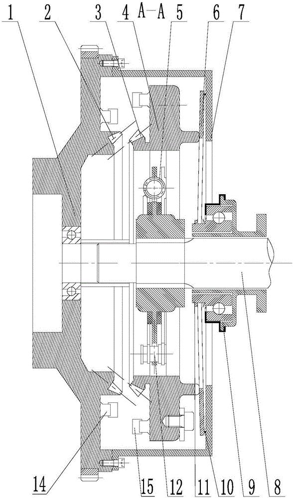
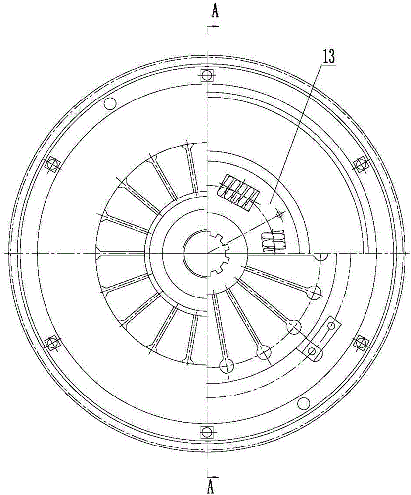
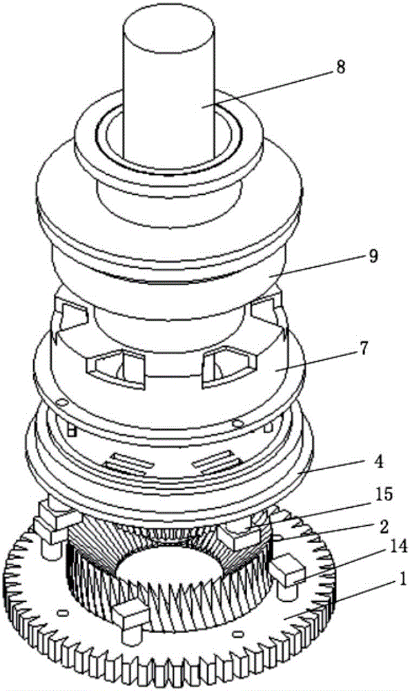
[0032] see Figure 1 to Figure 3 , the present invention is based on the high-speed inspired clutch of bevel gear internal meshing, including a flywheel 1, a shaft 8, and a pressure plate 4 and a release bearing 9 that are sequentially sleeved on the shaft 8 from left to right; wherein, the end face of the flywheel 1 is welded The internal bevel gear 2 moves synchronously with it; the internal bevel gear 2 can mesh with the bevel gear 3 under the closing action of the clutch; the bevel gear 3 is welded on the end surface of the pressure plate 4 to move synchronously; the shock absorber spring 5 is located The internal vibration damping part of the vibration damper 13; the internal hollow of the vibration damper 13 is sleeved on the shaft 8, and the vibration damper 13 is close to the bevel gear 3, which is use...


PUM


Abstract

The invention provides a high-rotating-speed starting clutch based on internal engagement of a bevel gear. The high-rotating-speed starting clutch based on internal engagement of the bevel gear comprises a flywheel, an internal bevel gear is welded to the flywheel structure, and the internal bevel gear and the flywheel structure move synchronously. The internal bevel gear can be engaged with the bevel gear under the closing effect of the clutch. The bevel gear is welded to a platen, and the bevel gear and the platen move synchronously. A shock absorber spring is located on the shock absorption portion in a shock absorber. The shock absorber is hollow, and the shaft is sleeved with the shock absorber. A diaphragm spring is mounted between the platen and a clutch cover, arranged on the shaft in a sleeving mode and makes contact with the protruding end of the platen. A release bearing is connected to the clutch cover and arranged on the shaft in a sleeving mode. The shock absorber is provided with a limiting pin. A driving rod is mounted on the platen, and a bearing and punching rod matched with the driving rod is mounted on a flywheel. According to the high-rotating-speed starting clutch, the clutch can be started at a high rotating speed finally based on internal engagement of the bevel gear and the clutch principle and through tight combination of all components; and the high-rotating-speed starting clutch has the characteristics that faults of a control system are reduced, the maintenance cost is low, the structure is simple, and the control stability is good.

Description

[0001] Technical field: [0002] The invention belongs to the technical field of high-speed inspiring clutch structures, and in particular relates to a high-speed inspiring clutch based on internal meshing of bevel gears. [0003] Background technique: [0004] At present, in the field of automobile clutches, the friction plate is connected to the flywheel to start the car at a low speed. When the clutch is started at a high speed, the friction plate will slip relatively and the car cannot be started, and even improper operation will cause the engine to stall. Moreover, starting at low speed is relatively fuel-intensive and the friction plates are prone to aging after a long time. Moreover, for some high-end racing cars and high-performance cars, low-speed starting affects the gear change time and leads to low vehicle starting efficiency. At the same time, there are some technical problems in the existing friction plate clutch, such as complex structure, complex control and poo...

Claims


Application Information

Patent Timeline
Patent Type & Authority Applications(China)
IPC IPC(8): F16D11/16
CPCF16D11/16
Inventor 张功学陈宁
Owner SHAANXI UNIV OF SCI & TECH
Learn More