Touch control display panel and touch control display device

A technology for touch display panels and display areas, applied in optics, instruments, electrical digital data processing, etc., can solve problems such as line afterimages, achieve the effect of improving line afterimages and reducing the number

Active Publication Date: 2017-05-17
XIAMEN TIANMA MICRO ELECTRONICS
View PDF19 Cites 15 Cited by
  • Summary
  • Abstract
  • Description
  • Claims
  • Application Information

AI Technical Summary

Problems solved by technology

[0005] The purpose of the present invention is to provide a touch display panel and a touch display device to solve the problem of line sticking caused

Method used


Image

  • Touch control display panel and touch control display device
  • Touch control display panel and touch control display device
  • Touch control display panel and touch control display device

Examples


Example Embodiment

[0029] The present invention will be further described in detail below in conjunction with the accompanying drawings and embodiments. It should be understood that the specific embodiments described herein are only used to explain the present invention, but not to limit the present invention. In addition, it should be noted that, for the convenience of description, the drawings only show some but not all structures related to the present invention.

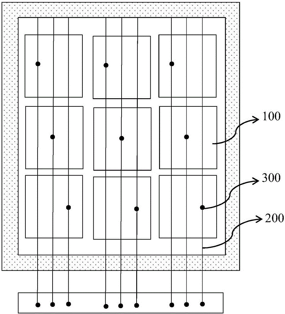
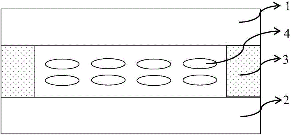
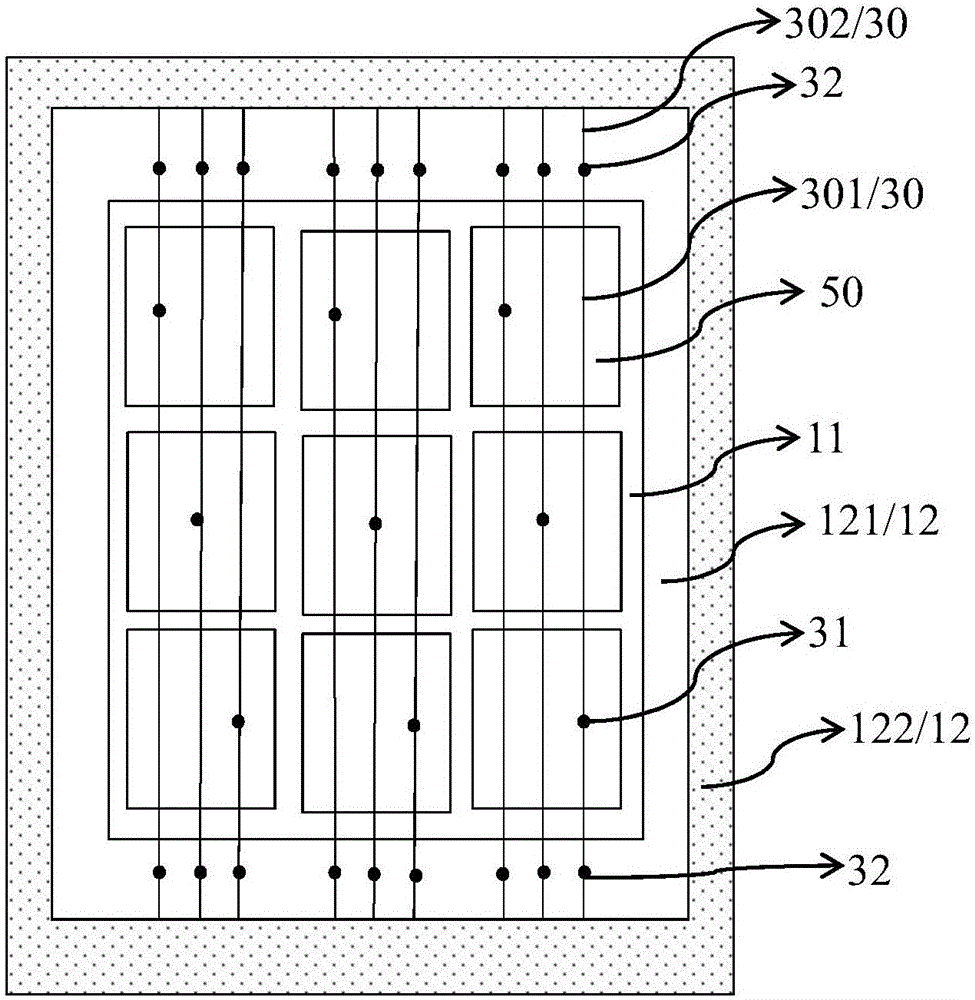
[0030] The present invention provides a touch display panel, comprising a touch electrode block, a touch signal line correspondingly connected to it through a bridge structure, the touch signal line including a first part located in a display area and a second part located in a non-display area part two. In the present invention, an auxiliary bridge structure is arranged on the second part of the touch signal line, and the auxiliary bridge structure is formed synchronously with the bridge structure located in the display area, and...


PUM


Abstract

The invention provides a touch control display panel and a touch control display device. The touch control display panel includes a touch control electrode block and a touch control signal line which is correspondingly connected with the touch control electrode block through a bridge structure; the touch control signal line includes a first part located in a display region and a second part located in an non-display region, an auxiliary bridge structure is arranged on the second part of the touch control signal line, impurity ions diffused from self-sealing frame adhesive are firstly diffused to the non-display region in which the auxiliary bridge structure is located, ionic pollution generated by the frame sealing adhesive is solved, the number of the impurity ions entering the display region is reduced, and accordingly the line blur phenomenon of the touch control display panel is further improved.

Description

technical field [0001] The present invention relates to the technical field of touch display, and in particular to a touch display panel and a touch display device. Background technique [0002] With the rapid development of display technology, touch display devices have gradually spread in people's daily life. At present, existing in-cell touch display devices use the principle of mutual capacitance or self-capacitance to detect the position touched by a finger. Among them, using the principle of self-capacitance, a plurality of self-capacitance electrodes arranged on the same layer and insulated from each other can be arranged in the touch display device. When the human body touches the screen, the capacitance borne by the corresponding self-capacitance electrodes is a fixed value superimposed on the human body capacitance. The integrated circuit for touch control in the drive unit can judge the touch control by detecting the capacitance value changes of the respective ca...

Claims


Application Information

Patent Timeline
IPC IPC(8): G02F1/1333G06F3/041
CPCG02F1/13338G06F3/0412
Inventor 吴薇黄强灿伍黄尧
Owner XIAMEN TIANMA MICRO ELECTRONICS
Why Eureka
Try Eureka