Beautified slot dipole antenna

A slot antenna and antenna technology, which is applied in the direction of slot antenna, resonant antenna, antenna grounding switch structure connection, etc., can solve the problems of difficult bending, easy to protrude, affect the appearance, etc., achieve good omnidirectional radiation characteristics, and improve the effect of bandwidth

Inactive Publication Date: 2017-05-17
GUANGDONG UNIV OF TECH
View PDF8 Cites 0 Cited by
  • Summary
  • Abstract
  • Description
  • Claims
  • Application Information

AI Technical Summary

Problems solved by technology

[0002] Most of the existing slot antennas need a larger width to ensure the bandwidth, which affects the appearance
In addition, some existing antenna devices designed with micro-slits often let the slit intersect with the edge of the metal surface to form an opening, or let the slit cut two edges to form two openings, and the opening is difficult to bend and easy to protrude , affecting the aesthetics of the antenna
Moreover, the positions of the slots of these antenna devices are limited, they need to be close to the edge of the metal surface to intersect with it, and cannot be moved to the center of the entire metal surface
In addition, from the principle of radiation, these antenna devices are not slot dipole antennas, and cannot produce omnidirectional radiation in the plane perpendicular to the slot

Method used


Image

  • Beautified slot dipole antenna
  • Beautified slot dipole antenna
  • Beautified slot dipole antenna

Examples


Embodiment Construction

[0011] The present invention will be further described in detail below in conjunction with the accompanying drawings and specific embodiments.

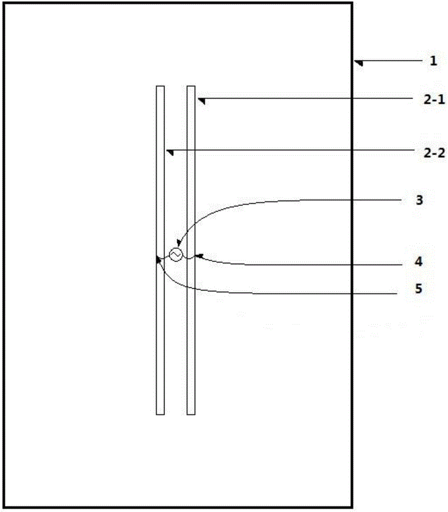
[0012] A beautifying slot antenna that can be widely used in the field of wireless communication is composed of a metal plane 1, more than two strip slots 2 and a radio frequency feeder 3. When the number of strip slots 2 is two, its structure is as follows attached figure 1 As shown, the ground terminal 4 and the excitation terminal 5 of the RF feeding terminal 3 are respectively connected to the farthest edges of the two slots 2-1 and 2-2.

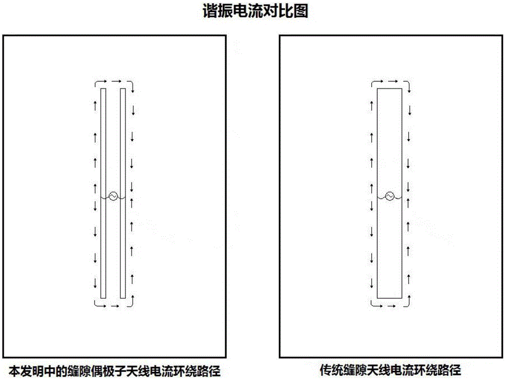
[0013] figure 2 Shown is the resonant current comparison diagram of slot dipole antenna among the present invention and traditional slot antenna; It can be seen that the current winding path of slot dipole antenna in the present invention is the same as the current winding path of traditional slot antenna, so Except for the area between the two slits, the current distribution on the metal pla...


PUM


Abstract

The invention provides a slot dipole antenna which is easy to process and produce, small in size, hidden and attractive. The slot dipole antenna consists of a metal plate, two strip-shaped slots and a radio frequency feed end; the antenna is a planar slot antenna; and in the metal plate, the grounding end and the excitation end of the radio frequency feed end are connected with edges, with the longest distance from each other, of the two strip-shaped slots respectively. The efficiency and radiation capability of the slot dipole antenna in each direction are close to those of a conventional slot antenna; and in addition, the actual size of the slot dipole antenna is greatly reduced, and the slot dipole antenna is attractive and can satisfy development tendency of the antenna.

Description

technical field [0001] The invention belongs to the radio field, and is especially applied to mobile phone antennas. Background technique [0002] Most of the existing slot antennas require a relatively large width to ensure the bandwidth, which affects the appearance. In addition, some existing antenna devices designed with micro-slits often make the slit intersect with the edge of the metal surface to form an opening, or the slit cuts two edges to form two openings, and the opening is difficult to bend and easy to protrude , affecting the aesthetics of the antenna. Moreover, the positions of the slots of these antenna devices are limited, and they need to be close to the edge of the metal surface to intersect with it, and cannot be moved to the center of the entire metal surface. In addition, from the radiation principle, these antenna devices are not slot dipole antennas, and cannot generate omnidirectional radiation in a plane perpendicular to the slot. Contents of t...

Claims


Application Information

Patent Timeline
Patent Type & Authority Applications(China)
IPC IPC(8): H01Q1/50H01Q13/10H01Q9/16
CPCH01Q1/50H01Q9/16H01Q13/10
Inventor 梁志鹏
Owner GUANGDONG UNIV OF TECH
Why Eureka
Try Eureka