Electromagnetic control delay booster electric pressure cooker

A technology of boosting voltage and electromagnetic control, applied in pressure cookers, kitchen utensils, household utensils, etc., can solve problems such as poor cooking effect

Inactive Publication Date: 2017-05-24
陆一铭
View PDF5 Cites 58 Cited by
  • Summary
  • Abstract
  • Description
  • Claims
  • Application Information

AI Technical Summary

Problems solved by technology

[0003] The purpose of the present invention is to provide a kind of electric pressure cooker that when cooking rice, after the rice boils, part of the steam in the pot will be discharged, and the rice grains in the pot will continue to boil under the half-high pressure state, forcing the rice grains to quickly absorb water under the half-high pressure state After the set time is reached, the air outlet is

Method used


Image

  • Electromagnetic control delay booster electric pressure cooker
  • Electromagnetic control delay booster electric pressure cooker
  • Electromagnetic control delay booster electric pressure cooker

Examples


Embodiment 1

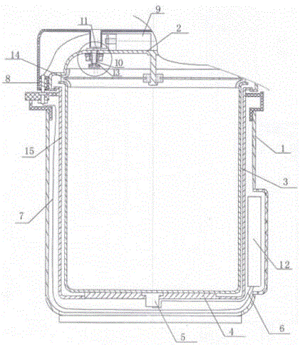
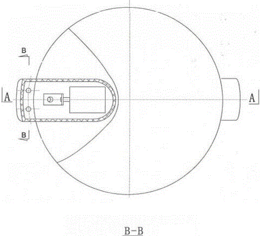
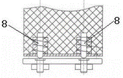
[0035] Such as figure 1 , 2 , 3, and 4, the pot cover 2 and the pot body 1 adopt a split structure, that is, when the pot cover 2 and the pot body 1 are rotated to the open position, the pot cover 2 will be completely separated from the pot body 1; 1 and the closed position of the pot cover 2 are provided with a spring contact connection mechanism, which ensures that the line control mechanism 12 and the input cable of the electromagnet 9 are in the connected state at the closed position of the pot body 1 and the pot cover 2; The contact connection mechanism includes two fixed contacts fixed on the side of the pot body 1, and two movable contacts 8 pushed out by spring force are arranged at the corresponding positions of the pot cover 2, and when the pot body 1 and the pot cover 2 are closed, position, the contacts 8 ejected by the spring are respectively connected to the fixed contacts on the side of the pot body 1, and the input cable 7 of the line control mechanism 12 and ...

Embodiment 2

[0037] Such as Figure 5 , 6, 7, 8, and 9, the pot cover 2 and the pot body 1 are a hinged structure hinged with a hinge 20, the pot cover 2 is turned upwards and opened, and a cable connecting the pot cover 2 and the pot body 1 is provided at the hinged position , to ensure that the line control mechanism 12 is connected with the electromagnet 9 through the cable. Figure 5 , 8 , 9 shows the position of the limit float of this embodiment, the float limit block 11 is directly connected to the electromagnet 9, forming a structure that is driven by the electromagnet 9 to slide on the pot cover 2, and the float limit block 11 is provided with a The hole through which the float passes; at the position of the limit float, the bottom of the float stop block 11 blocks the float and restricts the rise of the float to keep the steam in the pot leading to the atmosphere through the float vent hole 10; at the position of releasing the float, the float stop block 11 The hole opened for...

Embodiment 3

[0039] like Figure 10 , 11 , 12, 13, and 14, the float stop block 11 is connected with the pot cover 2 to form a sliding structure, and the float stop block 11 has a hole for the float to pass through; The ejection slide 16 of the two working positions, the ejection slide 16 is connected with the float stopper 11, so that when the ejection slide 16 moves to the position of ejection and recovery, the float stopper 11 is driven They are respectively in the position of limit float or release float. The float stopper 11 is provided with a spring force device, and the spring force of the device drives the float stopper 11 to always be pressed against the ejection and return ejection surfaces of the two working positions of the ejection slide 16 . The spring force device comprises a guide rod 18 socketed with the float stop block 11, the guide rod 18 is fixed on the pot cover, and a spring 19 is sleeved at the guide rod 18, and the movable end of the spring 19 tops the float stop...


PUM


Abstract

Disclosed is an electromagnetic control delay booster electric pressure cooker. A floater limited block is connected with an electromagnet, and the electromagnet drives the floater limited block to the position of the limiting floater or the releasing floater. At the position of the limited floater, the floater limited block blocks the floater, and limits the rising of the float, keeping expelling the steam in the cooker to the atmosphere through the vent hole of the floater; At the position of the releasing floater, the floater rises and falls freely; the line control institutions are provided with a delay control unit to control the electromagnet, and start the delay unit to control the work of the electromagnet in the specified delay time when the temperature of the temperature detector rises to the set delay startup time. The cooker has the advantages that: when the electric pressure cooker is cooking rice, the cooker releases partial steam insides after the rice boiling, and grain of rice in the cooker continues boiling in the condition of half a high-pressure, forcing the grain of rice absorb moisture quickly; close the outlet after reaching the set time, making the pressure in the cooker rises; shut off the power and keep heat to cook the rice. In this way, the rice grain is through core, chewiness and smooth when entering the mouth.

Description

technical field [0001] The invention relates to the technical field of electric pressure cookers, in particular to an electromagnetically controlled time-delay boost electric pressure cooker. Background technique [0002] When the traditional electric pressure cooker is heated normally, its gas outlet safety valve is closed. Because of safety requirements, when the food in the pot reaches boiling, pressure will be generated in the pot. If the pressure is too high, the gas outlet safety valve will be pushed to reduce the pressure in the pot. Release and cut off the power supply, use the temperature in the pot to continue cooking, when the temperature in the pot drops and the pressure decreases, turn on the power supply and reheat, and so on, until the food is cooked. This cooking process can be used for cooking soup. It saves electricity and time, and is convenient, but the effect is not very good for cooking rice, because the rice just boils in the pot, and the electric pres...

Claims


Application Information

Patent Timeline
IPC IPC(8): A47J27/08A47J36/38
CPCA47J27/08A47J27/0802A47J36/38
Inventor 陆一铭
Owner 陆一铭
Why Eureka
Try Eureka