Electric clipper

A shearer and electric technology, applied in the field of disaster relief equipment, can solve the problem of oil circuit circulating in one direction, etc., and achieve the effect of improving work efficiency

Inactive Publication Date: 2017-05-24
HANGZHOU ZHONGDUO FIRE FIGHTING SCI & TECH
View PDF7 Cites 1 Cited by
  • Summary
  • Abstract
  • Description
  • Claims
  • Application Information

AI Technical Summary

Problems solved by technology

[0004] In order to overcome the problem that the oil circuit of the existing hydraulic shearer can only circu

Method used


Image

  • Electric clipper
  • Electric clipper
  • Electric clipper

Examples


Embodiment Construction

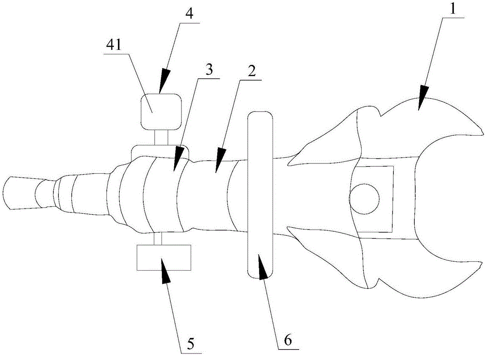
[0042] Such as figure 1 As shown, the electric shear provided in this embodiment includes a cutter 1 , a hydraulic drive assembly 2 , a reversing assembly 3 and an oil inlet assembly 4 . The hydraulic drive assembly 2 is connected to the cutter 1 to drive the cutter 1 to move. The reversing assembly 3 is connected with the hydraulic drive assembly 2 and provides the hydraulic drive assembly 2 with two oil circulations in opposite directions. The oil inlet assembly 4 is connected with the reversing assembly 3 .

[0043] In this embodiment, the hydraulic drive assembly 2 includes an oil cylinder 21 , an oil cylinder piston 22 and a connecting rod. The oil cylinder 21 is connected with the reversing assembly 3 . The oil cylinder piston 22 is arranged in the oil cylinder 21, and the oil pressure in the oil cylinder 21 pushes the oil cylinder piston 22 to move. One end of the connecting rod is connected with the cylinder piston 22, and the other end is connected with the cutter...


PUM


Abstract

The invention provides an electric clipper. The electric clipper comprises a pair of cutting nippers, a hydraulic driving assembly, a reversing assembly and an oil inlet assembly. The hydraulic driving assembly is connected to the pair of cutting nippers to drive the cutting nipper to move. The reversing assembly is connected to the hydraulic driving assembly to provide two oil path cycles opposite in direction to the hydraulic driving assembly. The oil inlet assembly is connected to the reversing assembly. According to the electric clipper provided by the invention, the reversing assembly is additionally arranged to change the direction of the oil path entering the hydraulic driving assembly, so that an oil cylinder piston in the hydraulic driving assembly can reciprocate freely so as to automatically feed oil and return oil without a manual operation, and therefore, the work efficiency of the electric clipper is greatly improved.

Description

technical field [0001] The invention relates to the technical field of disaster relief equipment, and in particular to an electric shear. Background technique [0002] Hydraulic shears are widely used in the rescue of traffic accidents such as highways and railways, earthquake disaster rescue, building collapse rescue, air and sea disaster rescue, and can cut vehicle components, metal structural pipes, special-shaped steel and plates. As an indispensable instrument for emergency rescue and disaster relief, how to improve the shearing function and use effect of the shearer has become an important issue to be considered in the process of emergency rescue and disaster relief. At the same time, how to make the shearer have multiple functions and adapt to different dangers These have become issues that society needs to constantly consider in order to promote technological development. [0003] After the oil circuit in the existing hydraulic shearer enters the hydraulic cylinder ...

Claims


Application Information

Patent Timeline
IPC IPC(8): B23D29/00
CPCB23D29/00
Inventor 王俊
Owner HANGZHOU ZHONGDUO FIRE FIGHTING SCI & TECH
Why Eureka
Try Eureka