Eureka AIR delivers breakthrough ideas for toughest innovation challenges, trusted by R&D personnel around the world.

Automatic mechanical arm structure of numerical control machine tool

A technology of CNC machine tools and manipulators, applied in the field of CNC machine tools, can solve the problems of large machine tool space, inconvenient maintenance, complex structure, etc., and achieve the effects of high work efficiency, compact structure, and stable lifting and translation.

Inactive Publication Date: 2017-05-24
宁波北仑牧田机械有限公司
View PDF0 Cites 5 Cited by
  • Summary
  • Abstract
  • Description
  • Claims
  • Application Information

AI Technical Summary

Problems solved by technology

[0002] CNC machine tools are commonly used equipment in industrial machining. Most of the existing CNC machine tools are processed manually. With the increase of labor costs, many CNC machine tools use manipulators to automatically load and pick up parts. However, the existing The structure of the manipulator is mostly complex, occupying a relatively large space on the machine tool and inconvenient to maintain

Method used


Image

  • Automatic mechanical arm structure of numerical control machine tool
  • Automatic mechanical arm structure of numerical control machine tool
  • Automatic mechanical arm structure of numerical control machine tool

Examples


Embodiment Construction

[0014] Below in conjunction with specific embodiment, further illustrate the present invention. It should be understood that these examples are only used to illustrate the present invention and are not intended to limit the scope of the present invention. In addition, it should be understood that after reading the teachings of the present invention, those skilled in the art can make various changes or modifications to the present invention, and these equivalent forms also fall within the scope defined by the appended claims of the present application.

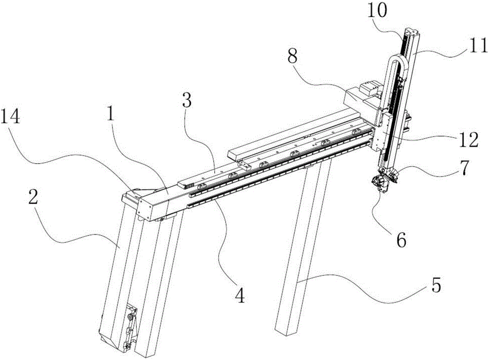
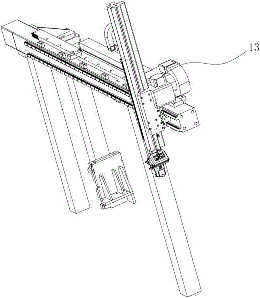
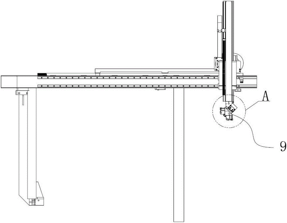
[0015] Such as Figure 1-4 As shown, the embodiment of the present invention relates to an automatic manipulator structure of a numerically controlled machine tool, comprising a beam 1 and a ram block 12, the upper end surface of the beam 1 is equipped with a transverse rack bar 3, and the front end of the beam 1 A pair of slide rails 4 are arranged side by side. The ram block 12 is erected on the slide rail 4 and translates a...


PUM


Abstract

The invention relates to an automatic mechanical arm structure of a numerical control machine tool. The automatic mechanical arm structure comprises a cross beam and a ram block. A transverse rack rod is arranged on the upper end face of the cross beam. A pair of sliding rails is arranged on the front end face of the cross beam side by side. The ram block is erected on the sliding rails and horizontally moves along the sliding rails. A vertical beam ascending and descending up and down is vertically arranged on the ram block. A lifting motor is transversely arranged on the ram block. A gear on an output shaft of the lifting motor is engaged with a vertical rack rod on one side of the vertical beam. A horizontally-moving motor is vertically arranged on the ram block. A gear on an output shaft at the lower end of the horizontally-moving motor is engaged with the transverse rack rod, and a rotational mechanical arm is arranged at the lower end of the vertical beam. The automatic mechanical arm structure is compact in structure, less numerical control machine tool space is occupied, ascending, descending and horizontal moving are relatively stable, a workpiece can be clamped to a machine tool spindle when the automatic mechanical arm structure takes the workpieces, and the working efficiency is high.

Description

technical field [0001] The invention relates to the field of numerical control machine tools, in particular to an automatic manipulator structure of a numerical control machine tool. Background technique [0002] CNC machine tools are commonly used equipment in industrial machining. Most of the existing CNC machine tools are processed manually. With the increase of labor costs, many CNC machine tools use manipulators to automatically load and pick up parts. However, the existing Most of the manipulator structures are complex in structure, occupy a relatively large machine tool space, and are inconvenient to maintain. Contents of the invention [0003] The technical problem to be solved by the present invention is to provide an automatic manipulator structure of a CNC machine tool, which has a compact structure, occupies a relatively small space of the CNC machine tool, and is relatively stable in lifting and translation, and can clamp the workpiece on the machine tool spin...

Claims


Application Information

Patent Timeline
IPC IPC(8): B23Q7/04
CPCB23Q7/04B23Q7/043
Inventor 李士龙
Owner 宁波北仑牧田机械有限公司
Why Eureka
Eureka Blog
Learn More