Manufacturing process of resin frame

A production process and technology of mirror frames, applied in the field of glasses, can solve the problem of inability to adjust the curvature of the mirror frame, and achieve the effect of convenient user operation, enhanced user experience, and convenient and free adjustment.

Active Publication Date: 2019-03-01
广州邦士度眼镜有限公司
View PDF6 Cites 0 Cited by
  • Summary
  • Abstract
  • Description
  • Claims
  • Application Information

AI Technical Summary

Problems solved by technology

[0003] The present invention aims at the disadvantage that the radian of the frame cannot be adjusted in the prior art, and provides a manufacturing process of the resin frame

Method used


Image

  • Manufacturing process of resin frame

Examples


Embodiment 1

[0036] The manufacturing process of the resin frame, as shown in the figure, includes the following steps:

[0037] 1) Design mold: design a pair of mirror frames and a pair of temples that match the frames;

[0038] 2) Mold making: Make the molds of the set mirror frame and mirror feet;

[0039] 3) Debugging the mold: Repeat the mold adjustment and mold trial after the mold has been made, and then proceed to the next step of installation after reaching the standard;

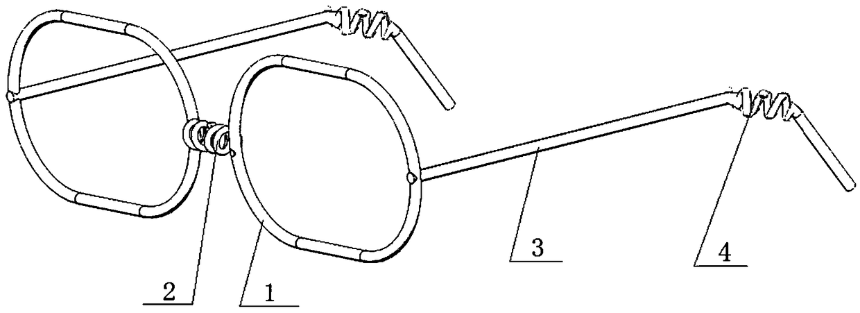
[0040] 4) Make the keel: make the picture frame keel and the mirror foot keel, the picture frame keel includes two ring frames 1 for placing the lenses and the nose frame 2 connecting the ring frame 1, the mirror foot keel includes the long rod frame 3 and the long rod frame 3 connected The ear frame 4, the ring frame 1 and the long rod frame 3 are all made by bending straight steel wires, and the nose frame 2 and the ear frame 4 are all made of spiral steel wires;

[0041] 5) Install the keel: fix the finishe...

Embodiment 2

[0062] The difference from Example 1 is that part of the outer surface of the mold is wrapped with thermal insulation cotton, and the part where the nose frame 2 and ear frame 4 are installed on the mold is defined as a flexible forming part, and the outer surface of the flexible forming part is exposed, and then the Put the mold into the cooling chamber and cool it at -32°C for 30 minutes, then put the mold at room temperature for 150 minutes, then heat the flexible molding part through the heating spray gun and make the temperature reach 92°C, then put it into the cooling chamber and cool it at -7 Cool at ℃ for 62 minutes, take out the mold and place it at room temperature. After the mold returns to room temperature, open the mold and take out the mirror frame and temples.

Embodiment 3

[0064] The difference from Example 1 is that part of the outer surface of the mold is wrapped with thermal insulation cotton, and the part where the nose frame 2 and ear frame 4 are installed on the mold is defined as a flexible forming part, and the outer surface of the flexible forming part is exposed, and then the Put the mold into the cooling chamber and cool it at -37°C for 25 minutes, then place the mold at room temperature for 150 minutes, then heat the flexible molding part through the heating spray gun and make the temperature reach 92°C, then put it into the cooling chamber and cool it at -7 Cool at ℃ for 62 minutes, take out the mold and place it at room temperature. After the mold returns to room temperature, open the mold and take out the mirror frame and temples.


PUM


Abstract

The invention relates to glasses and discloses a manufacturing process for a resin optical frame. The manufacturing process comprises the following steps: designing a die; manufacturing the die; debugging the die; manufacturing a keel; mounting the keel: fixing a well manufactured optical frame keel and glasses leg keels in the die for preparing injection molding; performing injection molding; molding; performing manual surface treatment; spraying; assembling; labeling; correcting the frame; cleaning; inspecting; and packaging and storing. Spiral steel wire keels are arranged on a nose frame and ear frames of the glasses and are matched with a second resin material, such that the frame body at a nose support and ear supports can be twisted freely, the optical frame has well elasticity, is difficult to fracture and damage and is suitable for glasses wearers with different nose forms and face forms, the wearers can conveniently adjust a radian of the glasses, and user experience is enhanced.

Description

technical field [0001] The invention relates to glasses, in particular to a manufacturing process of a resin mirror frame. Background technique [0002] In daily study and life, students are under more and more pressure to study, and a lot of writing will affect students' body and mood, which will cause many students to appear myopia, but it is very difficult to find a pair of suitable glasses. It is not easy and brings inconvenience to the students. Ordinary glasses need to be adjusted by a professional optical shop through professional instruments, which makes the adjustment of the frame very inconvenient and cannot be adjusted arbitrarily according to the needs of users. Contents of the invention [0003] Aiming at the defect that the radian of the picture frame cannot be adjusted in the prior art, the invention provides a manufacturing process of the resin picture frame. [0004] In order to solve the above technical problems, the present invention is solved through t...

Claims


Application Information

Patent Timeline
Patent Type & Authority Patents(China)
IPC IPC(8): B29D12/02G02C13/00
CPCB29D12/02G02C13/00G02C13/001
Inventor 陈邦宋
Owner 广州邦士度眼镜有限公司
Why Eureka
Try Eureka