
Hardware steel bar bending device

A kind of bending device, technology of metal steel

Inactive Publication Date: 2020-06-16
田清
View PDF0 Cites 2 Cited by
  • Summary
  • Abstract
  • Description
  • Claims
  • Application Information

AI Technical Summary

Problems solved by technology

For the bending of hardware materials, most of them are bending operations of hardware steel bars. For the bending of hardware steel bars, the market mainly includes automatic bending machines and manual bending machines. When the steel bar is bent, the bending angle can be changed randomly, which is convenient for adjusting the bending arc, but it requires a lot of labor to produce, the production efficiency is low, and the production cost is high, while the production efficiency of the automatic bending machine High, but because the hardware steel bar itself has a certain hardness, after long-term production and use, it may cause some parts of the automatic bending machine to wear out, affecting the bending arc accuracy of the bending device, and the traditional automatic bending machine The bending machine does not have the function of cutting the bending part, that is to say, other devices are needed to complete the bending of the metal steel bar, which affects the production speed

Method used

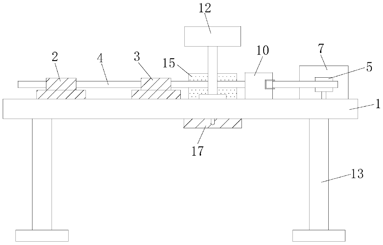
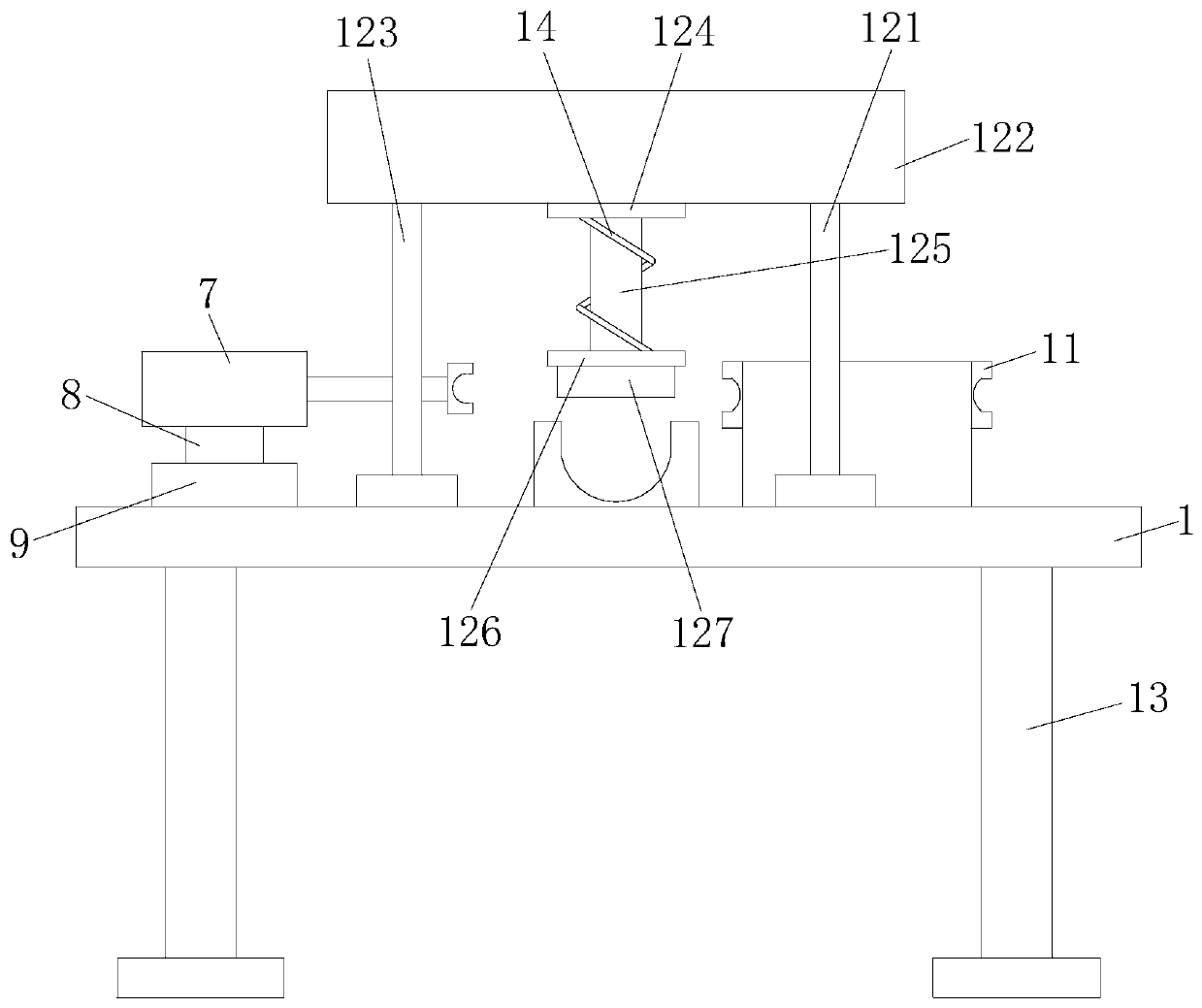
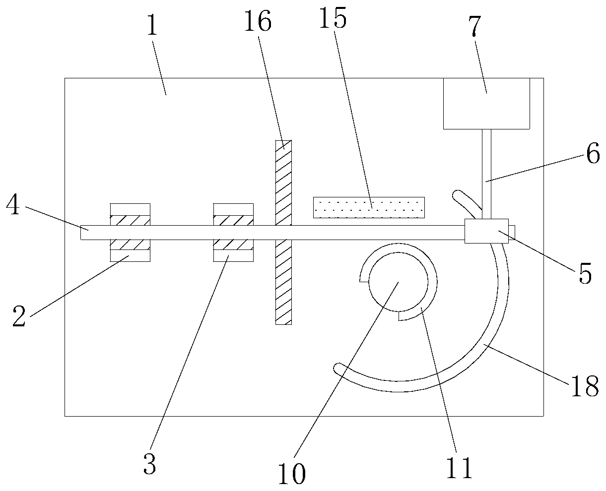

Image

  • Hardware steel bar bending device
  • Hardware steel bar bending device
  • Hardware steel bar bending device

Examples


Embodiment Construction

[0021] The following will clearly and completely describe the technical solutions in the embodiments of the present invention with reference to the accompanying drawings in the embodiments of the present invention. Obviously, the described embodiments are only some, not all, embodiments of the present invention. Based on the embodiments of the present invention, all other embodiments obtained by persons of ordinary skill in the art without making creative efforts belong to the protection scope of the present invention.

[0022] see Figure 1-4 , the present invention provides a technical solution: a hardware steel bar bending device, including a table body 1, the top left side of the table body 1 is fixedly connected with a first steel bar fixing seat 2, and the right side of the first steel bar fixing seat 2 The side is provided with a second steel bar fixing seat 3, and one end of the second steel bar fixing seat 3 is fixedly connected to the top side of the table body 1, an...


PUM


Abstract

The invention discloses a hardware steel bar bending device, and relates to the field of hardware steel bar bending devices. The hardware steel bar bending device comprises a table body, a first steelbar fixing seat is fixedly connected to the left side of the top end of the table body, a second steel bar fixing seat is arranged on the right side of the first steel bar fixing seat, one end of thesecond steel bar fixing seat is fixedly connected to one side of the top end of the table body, a hardware steel bar is connected to one end of the first steel bar fixing seat and one end of the second steel bar fixing seat in a clamped mode, a push block is connected to the other end of the hardware steel bar in a clamped mode, a semicircular sliding groove is connected to one end of the push block in a clamped mode, an electric push rod is fixedly connected to one end of the push block, the other end of the electric push rod is sleeved with a ground hole push rod box, and the bottom end ofthe electric push rod box is fixedly connected with a circular rotating block. According to the hardware steel bar bending device, micro-heating treatment can be carried out on hardware steel bars, sothat the hardware steel bars are soft and high in plasticity, and bending and cutting the hardware steel bars are conveniently carried out.

Description

technical field [0001] The invention relates to the technical field of hardware steel bar bending devices, in particular to a hardware steel bar bending device. Background technique [0002] Hardware materials can be seen everywhere in our daily life. Hardware materials can be used in various industries, from small household items to large construction projects and metal installations and equipment. When using hardware materials, it is often necessary to pretreat the hardware materials according to requirements, and the pretreatment includes bending, grinding and other operations. For the bending of hardware materials, most of them are bending operations of hardware steel bars. For the bending of hardware steel bars, the market mainly includes automatic bending machines and manual bending machines. When the steel bar is bent, the bending angle can be changed randomly, which is convenient for adjusting the bending arc, but it requires a lot of labor to produce, the productio...

Claims


Application Information

Patent Timeline
Patent Type & Authority Applications(China)
IPC IPC(8): B21D7/024B21D7/16B21D43/28B21D55/00F16F15/067
CPCB21D7/024B21D7/162B21D43/285B21D55/00F16F15/067
Inventor 田清
Owner 田清
Learn More