Engine oil control valve for end part oil supply

An oil control valve and oil supply technology, applied in the direction of controlling the pressure of lubricant, valve device, mechanical equipment, etc., can solve the problems of high requirements on mechanical strength of the filter screen and failure of the filter, so as to reduce the mechanical strength requirements and reduce the Small bending stress, the effect of meeting oil supply requirements

Inactive Publication Date: 2017-05-24
SCHAEFFLER TECH AG & CO KG
View PDF0 Cites 1 Cited by
  • Summary
  • Abstract
  • Description
  • Claims
  • Application Information

AI Technical Summary

Problems solved by technology

[0007] The problem to be solved by the present invention is: the existing oil control valve for oil supply at the end has higher requirements on the mechanical strength of the filter screen in the filter. In addition, when the filter holes of the filter screen are severely blocked by impurities in the hydraulic oil, the filter There is a risk of failure of the actuator, resulting in little or no hydraulic fluid being supplied to the camshafts and phasers

Method used


Image

  • Engine oil control valve for end part oil supply
  • Engine oil control valve for end part oil supply
  • Engine oil control valve for end part oil supply

Examples


no. 1 example

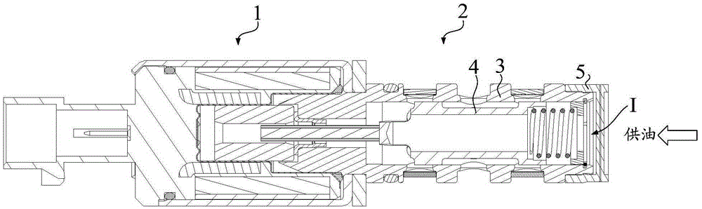
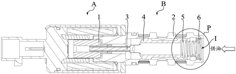
[0032] like image 3 As shown, the oil control valve of this embodiment includes two parts: a proportional solenoid A and a hydraulic body B. Among them, the proportional electromagnet A includes a movable armature 1 . The hydraulic body B includes a valve body 2, one axial end of the valve body 2 is fixedly connected with the proportional electromagnet A, and the other axial end has an oil inlet I. The valve body 2 is provided with a push rod 3 , a piston 4 , an elastic member 5 and a filter 6 arranged axially from the inside to the outside (that is, the direction from the proportional electromagnet A to the oil inlet I). One end of the push rod 3 is fixedly connected with the movable armature 1 , and the other end is fixedly connected with the piston 4 . The elastic member 5 is clamped between the piston 4 and the filter 6 in a compressed state. In this embodiment, the elastic member 5 is a coil spring. In the modification of this embodiment, the elastic member 5 can also ...

no. 2 example

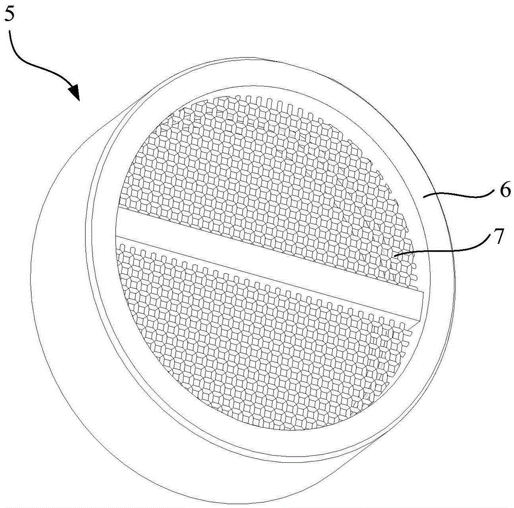
[0046] The difference between the second embodiment and the first embodiment is that in the second embodiment, the combination Figure 8 to Figure 9 As shown, there is no guide foot provided on the annular body portion 60 , and all the oil passages 64 do not pass through the annular body portion 60 in the axial direction B pointing to the piston 4 , that is, the oil passages 64 are in a closed ring shape. like Figure 9 As shown, when the annular body portion 60 moves to the point where the axially outer end of the annular body portion 60 is separated from the inner wall of the valve body 2 and is arranged radially opposite to the opening 22, the opening 22 and the inlet of the oil passage 64 are radially Overlapping, the hydraulic oil flowing in from oil inlet I follows Figure 6 The direction indicated by the dashed arrow in the middle flows through the groove 21 and the oil channel 64 on the annular main body 60 to the space in the valve body 2 axially inside the filter sc...


PUM


Abstract

The invention discloses an engine oil control valve for end part oil supply. The engine oil control valve for end part oil supply comprises a valve body with an air inlet port located in one end in the axial direction, a piston and a compressed-state elastic element which are located in the valve body and sequentially arranged in the axial direction, and a filter used for filtering hydraulic oil flowing towards the interior of the valve body from the air inlet port, wherein the filter comprises an annular main body part and a filter screen fixedly arranged on the annular main body part; and the filter is located in the valve body, and the elastic element is clamped and pressed between the piston and the annular main body part in the axial direction. The engine oil control valve further comprises a limit part and a groove which are arranged on and in the inner wall of the valve body, and an oil channel penetrating through the annular main body part in the radial direction, wherein the limit part is located at one side facing the air inlet port, of the filter, the opening of the groove is located between the limit part and the piston in the axial direction, and the opening is formed in a manner of being spaced from the limit part in the axial direction. In the technical scheme of the invention, the hydraulic oil can still be normally supplied to a camshaft and a phase adjustor even if the filter screen is seriously blocked. In addition, requirements on the mechanical strength of the filter screen are lowered.

Description

technical field [0001] The invention relates to the field of an oil control valve (OCV for short) used in a variable valve timing (Variable Valve Timing, VVT for short) system, in particular to an oil control valve for supplying oil at an end. Background technique [0002] The oil control valve is one of the core components of the variable valve timing system. According to the oil supply mode, the existing oil control valves are divided into two types: end oil supply oil control valves and side oil supply oil control valves. [0003] like figure 1 As shown, an existing oil control valve for oil supply at the end includes two parts: a proportional electromagnet 1 and a hydraulic body 2 . Wherein, the hydraulic body 2 includes a valve body 3, a piston 4 movably located in the valve body 3, and a filter 5, and the valve body 3 has an oil inlet I located at an axial end. [0004] combine Figure 1 to Figure 2 As shown, the filter 5 has an annular main body 6 and a filter scr...

Claims


Application Information

Patent Timeline
Patent Type & Authority Applications(China)
IPC IPC(8): F01L1/34F01M1/16F01M11/03
CPCF01L1/34F01M1/16F01M11/03
Inventor 张文豪
Owner SCHAEFFLER TECH AG & CO KG
Why Eureka
Try Eureka