Automatic gear shifting mechanism of wheel type mechanical walking excavator and wheel type mechanical walking excavator

An automatic shifting, excavator technology, applied in mechanical equipment, transmission control, belt/chain/gear, etc., can solve the problems of complicated manual shifting, inconvenient operation, difficult diagnosis, etc., to avoid damage to the transmission mechanism or even Produce safety accidents, simple structure and easy operation.

Active Publication Date: 2017-05-24
FUJIAN JINGONG MACHINERY
View PDF8 Cites 1 Cited by
  • Summary
  • Abstract
  • Description
  • Claims
  • Application Information

AI Technical Summary

Problems solved by technology

However, because the hydraulic excavator uses liquid as the medium, there are corresponding defects: severe heat generation, not suitable for long-distance walking; mechanical loss, pressure loss, and leakage loss in the transmission; sensitive to oil temperature, it is not suitable to use components at low or high temperatures, High manufacturing precision and high cost; it is difficult to diagnose when the device fails; etc.
Because the reliability of the flexible shaft or the pull rod mechanism is low, frequent maintenance is required; in addition, the manual shift method is more complicated and requires the skilled cooperation of the feet, which is inconvenient to operate. security incident

Method used


Image

  • Automatic gear shifting mechanism of wheel type mechanical walking excavator and wheel type mechanical walking excavator
  • Automatic gear shifting mechanism of wheel type mechanical walking excavator and wheel type mechanical walking excavator
  • Automatic gear shifting mechanism of wheel type mechanical walking excavator and wheel type mechanical walking excavator

Examples


Embodiment Construction

[0033] The present case will be described in further detail below in conjunction with the accompanying drawings and specific embodiments.

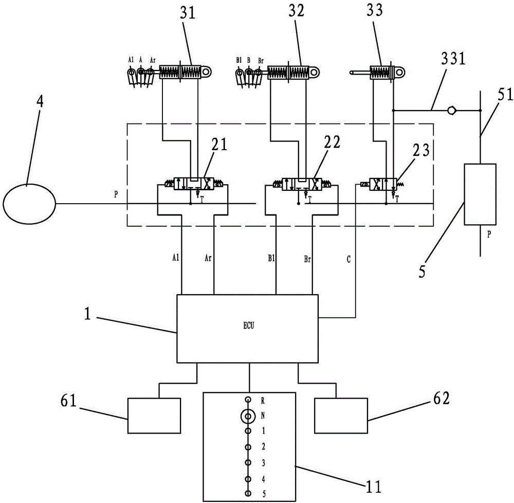
[0034] This case involves an automatic shift mechanism for a wheeled mechanical walking excavator, such as figure 1 As shown, it includes a control panel 1, a solenoid valve and a cylinder. Wherein, the solenoid valve includes solenoid valve A21 , solenoid valve B22 and solenoid valve C23 , and the cylinder includes shift cylinder A31 , shift cylinder B32 and clutch cylinder 33 .

[0035] The electrical connection terminals of the solenoid valve A21 , the solenoid valve B22 and the solenoid valve C23 are respectively electrically connected to the control terminal of the control panel 1 . The gas path connection ends of the solenoid valve A21, the solenoid valve B22 and the solenoid valve C23 are all connected to the gas path of the gas storage tank 4 of the excavator. The solenoid valve A21 is connected to the shifting cylinder A31, the...


PUM


Abstract

The invention discloses an automatic gear shifting mechanism of a wheel type mechanical walking excavator and the wheel type mechanical walking excavator. The mechanism comprises an operating panel, electromagnetic valves and air cylinders. The electromagnetic valves comprise an electromagnetic valve A, an electromagnetic valve B and an electromagnetic valve C. The air cylinders comprise a gear shifting air cylinder A, a gear shifting air cylinder B and a clutch air cylinder; the electromagnetic valve A, the electromagnetic valve B and the electromagnetic valve C are electrically connected to a control end of the operating panel, separately, and are in gas circuit connection to a gas storage tank of the excavator, and the electromagnetic valve A and the gear shafting air cylinder A, the electromagnetic valve B and the gear shafting air cylinder B and the electromagnetic valve C and the clutch air cylinder are in one-to-one-correspondence gas circuit connection, separately; a piston shaft of the gear shifting air cylinder A is connected to a gear shifting pull rod A of a transmission, and a piston shaft of the gear shifting air cylinder B is connected to a gear shifting pull rod B of the transmission. The mechanism disclosed by the invention realizes an automatic gear shafting operation of mechanical transmission, has the characteristics of being concise in structure, stable and reliable and simple to operate, and avoids the problems that the transmission mechanism is damaged as a result of malfunction due to operating inexperience, or even safety accidents are generated, are solved.

Description

technical field [0001] The invention relates to the field of wheeled mechanical walking excavators, in particular to an automatic shift mechanism of the wheeled mechanical walking excavator and the wheeled mechanical walking excavator. Background technique [0002] An excavator is an earth-moving machine that uses a bucket to dig materials higher or lower than the bearing surface, and loads them into transport vehicles or unloads them into the stockyard. Excavators have become one of the most important construction machinery in engineering construction. . According to different transmission methods, excavators can be divided into hydraulic walking excavators and mechanical walking excavators. Compared with mechanical transmission, hydraulic transmission is a new technology. Compared with wheeled mechanical walking excavators, hydraulic excavators have more components It has the advantages of flexible layout and installation, large-scale stepless speed regulation, and easy a...

Claims


Application Information

Patent Timeline
IPC IPC(8): F16H61/40F16H61/18F16H59/02F16H63/42
CPCF16H59/02F16H61/18F16H61/40F16H63/42
Inventor 詹小朋赵家宏邱国新丁后领吴景逸许世居柯金鐤柯水源
Owner FUJIAN JINGONG MACHINERY
Why Eureka
Try Eureka