
A gas pipe blockage detection device and blockage detection method

The technology of a detection device and detection method is applied in the pipeline system, gas/liquid distribution and storage, and by measuring the acceleration and deceleration rate of fluid, etc., and can solve the problems of complicated operation of the measurement device, long time required, and complicated on-site conditions, etc. Achieve the effect of reducing risk, improving efficiency and reducing the risk of gas leakage

Active Publication Date: 2019-01-04
CHONGQING GAS GRP CORP LTD
View PDF7 Cites 0 Cited by
  • Summary
  • Abstract
  • Description
  • Claims
  • Application Information

AI Technical Summary

Problems solved by technology

[0003] In the existing technology, in the process of inspection, due to the complicated operation of the measuring device, and in the process of plugging and detection, gas leakage is very easy to occur, and because in the construction site, especially the gas In emergency operations, there are different working conditions of various types of work, and the situation on site is relatively complicated. Once gas leakage occurs due to improper operation, it will cause quite serious accidents
[0004] Moreover, the existing inspection methods need to install an independent blocking device during the detection process and remove the blocking device during the pressure test. This process is complicated and repetitive, and it takes a long time during the test. , resulting in a low labor rate, and the traditional process requires hot work during installation and dismantling, making the process impossible to work in special areas

Method used


Image

  • A gas pipe blockage detection device and blockage detection method
  • A gas pipe blockage detection device and blockage detection method
  • A gas pipe blockage detection device and blockage detection method

Examples


Embodiment 1

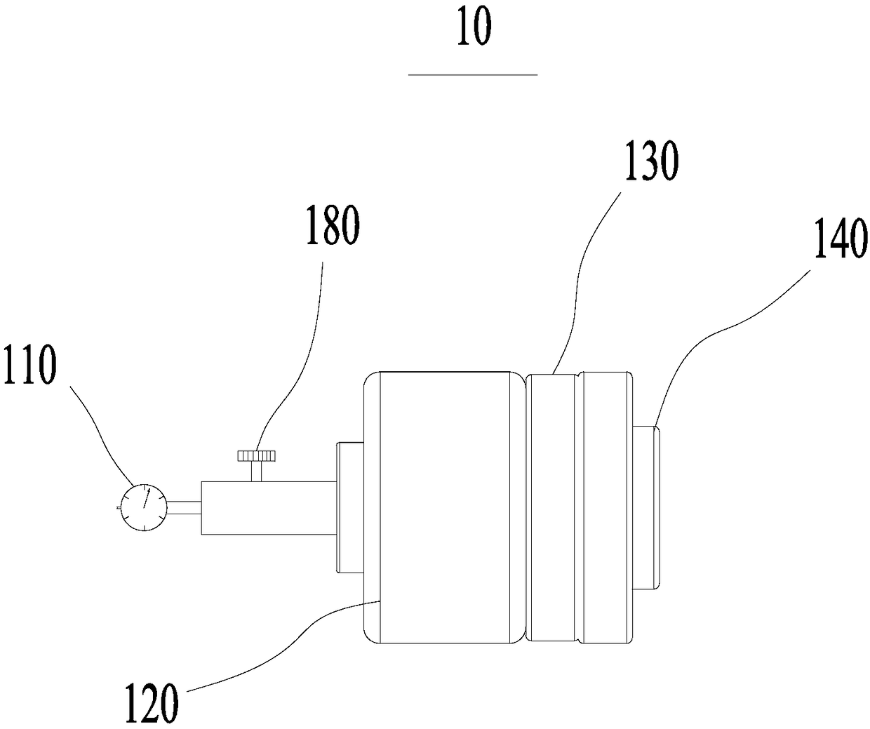
[0039] Please refer to figure 1 , figure 1 A gas pipe blockage detection device 10 which will be described in detail below is shown. It can be seen from the figure that the gas pipe blocking detection device 10 mainly includes a measuring device 110, a power device 120, an elastic pad 130, a pressure plate 140 and a valve 180.

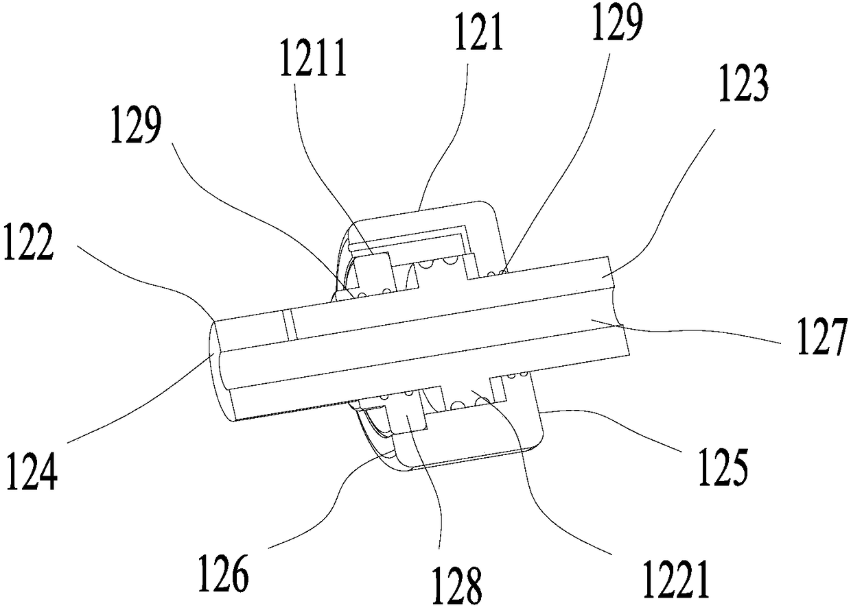
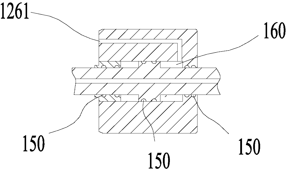
[0040] Please refer to figure 2 , figure 2 The main structure of the power unit 120 is shown. The power unit 120 mainly includes a cylinder block 121, a cylinder head 128, a piston 1221 and a piston rod 122. The cylinder block 121 has a hollow chamber inside, and the cylinder block 121 has a first end surface 125 and The second end surface 126 and the second end surface 126 are provided with a cylinder head mounting hole 1211 for installing the cylinder head 128, and the first end surface 125 and the cylinder head 128 are provided with a piston rod passing hole 129; the two ends of the piston rod 122 are respectively the first end 123 and the second end...


PUM


Abstract

The invention discloses a gas pipe blockage detection device and relates to the field of gas engineering. The gas pipe blockage detection device comprises a measurement device, a power device, an elastic cushion and a pressing plate. The power device comprises a cylinder body, a cylinder cover, a piston and a piston rod. A cavity is formed in the cylinder body. The cylinder body is provided with a first end face and a second end face. The piston rod comprises a first end and a second end. The piston is fixedly connected with the piston rod, and the piston rod penetrates the cylinder body. A gas guiding hole is formed in the piston rod in the axial direction. A valve for controlling the gas guiding hole to be connected and disconnected is arranged at the position, close to the second end, of the piston rod. The elastic cushion is arranged between the pressing plate and the first end face. The gas pipe blockage detection device is simple in structure, convenient to use and capable of effectively preventing leakage; and in addition, by means of the gas guiding hole in the piston rod, the gas pressure, gas and the like inside a blocked gas pipe can be measured precisely. Based on the gas pipe blockage detection device, the invention further provides a blockage detection method.

Description

Technical field [0001] The invention relates to the field of gas engineering, in particular to a gas pipe blockage detection device and a blockage detection method. Background technique [0002] In the process of overhaul and installation of gas pipes, in order to ensure the safety of gas transportation, it is necessary to check the gas pipe pressure and gas composition in the pipe to ensure that there is no leakage of the gas pipe and the safety of the construction process. Only qualified gas pipelines can be put into normal transmission and distribution operation. [0003] In the existing technology, during the inspection process, due to the complicated operation of the measuring device, and the process of plugging and testing, gas leakage is very easy to occur, and because of the construction site, especially the gas In the rescue operation, there are different working conditions for each type of work, and the on-site situation is more complicated. If the gas leak occurs due to...

Claims


Application Information

Patent Timeline
Patent Type & Authority Patents(China)
IPC IPC(8): G01M3/28F17D5/02
CPCF17D5/02
Inventor 侯俊刘镇朱曦张东杨庆辉蔺雪平卢涛万新江奕陈浩侯剑吴帆池骋史晓青汪岳睿陈铖赵惟翰杨怡恒张卓王鑫吴琳蒋博洲
Owner CHONGQING GAS GRP CORP LTD
Learn More