
Industrial and mining lamp assembly

A technology for high bay lamps and components, which is applied to the parts of lighting devices, semiconductor devices of light-emitting elements, and power supplies inside the machine, etc., can solve the problems of reduced installation efficiency, cumbersome and complicated installation process, increased torsional force, etc., and achieves reduced positioning. The use, installation or disassembly of components is convenient and the effect of installation operation is realized

Inactive Publication Date: 2017-05-24
GREE ELECTRIC APPLIANCES INC
View PDF4 Cites 6 Cited by
  • Summary
  • Abstract
  • Description
  • Claims
  • Application Information

AI Technical Summary

Problems solved by technology

With the increase in the number of modules, the types and quantities of components used to assemble high bay lights have greatly increased, resulting in increased material costs, cumbersome and complicated installation processes, and reduced installation efficiency.
At the same time, with the increase in the number of modules, the torsional force on the bolts or nuts at the various connection parts of the high bay lights increases significantly, resulting in more time-consuming and laborious locking or disassembly operations involved in the installation and disassembly process, resulting in more Labor cost and time cost input
Moreover, when assembling the integrated module, it is often necessary to modify the mounting bracket according to factors such as the actual volume and weight of the lamp body. This process is time-consuming and laborious, with high labor costs and low production efficiency.

Method used


Image

  • Industrial and mining lamp assembly
  • Industrial and mining lamp assembly
  • Industrial and mining lamp assembly

Examples


Embodiment Construction

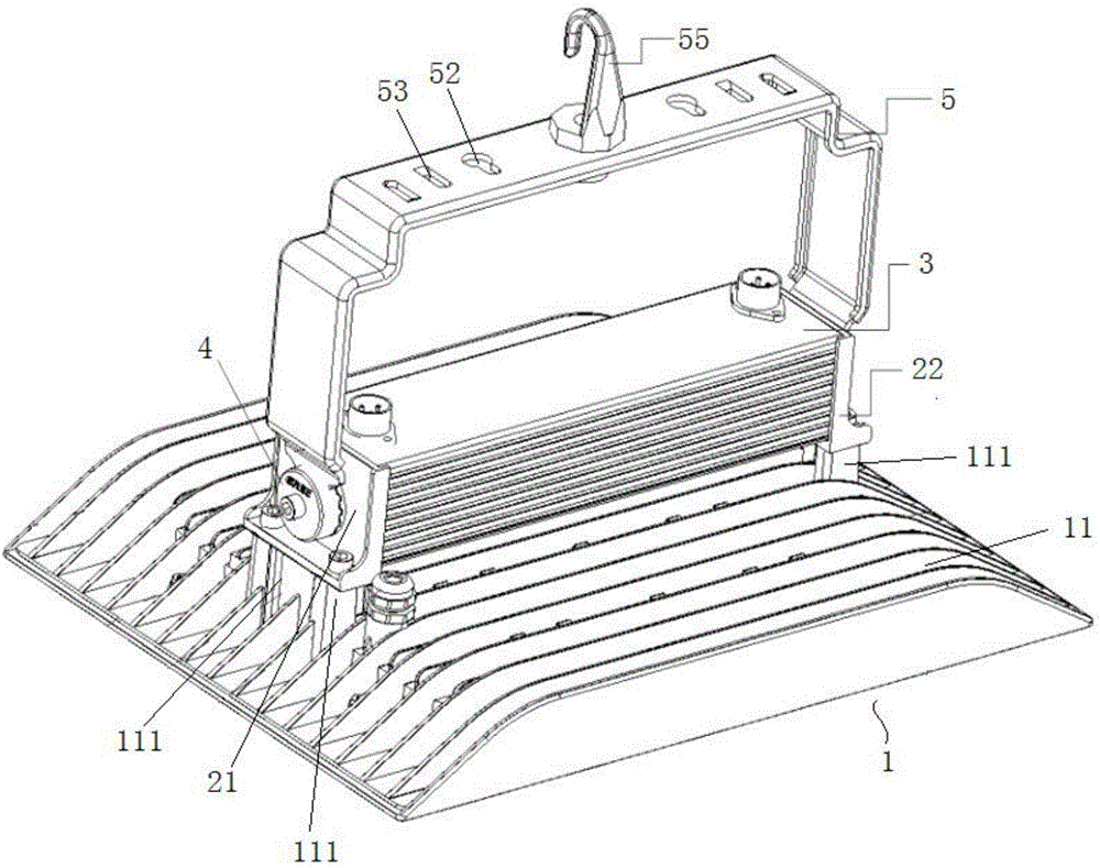
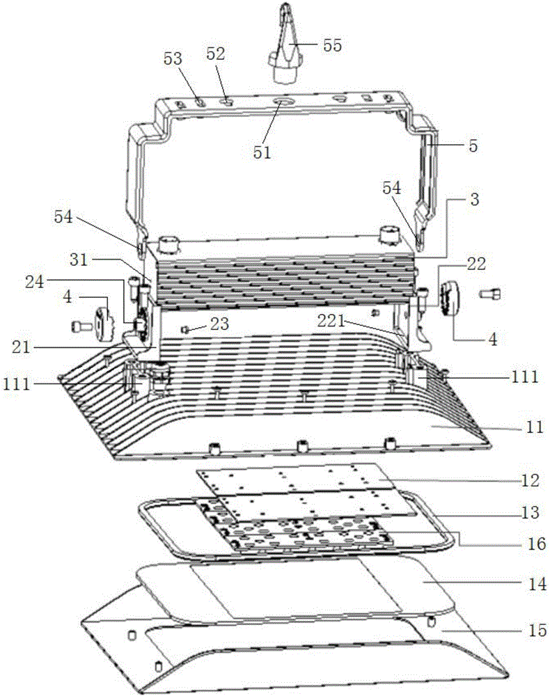
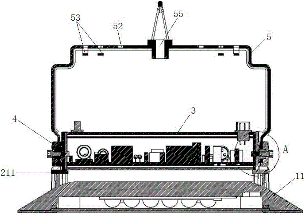
[0044] In order to further explain the technical means and functions adopted by the present invention to achieve the predetermined purpose, the specific implementation, structure, features and functions of the application according to the present invention will be described in detail below in conjunction with the accompanying drawings and preferred embodiments. In the following description, particular features, structures, or characteristics of one or more embodiments may be combined in any suitable manner.

[0045] This specific embodiment relates to a high bay lamp assembly, including:

[0046] A high bay lamp 1, the high bay lamp 1 includes a connection housing 11, and a lamp body connected to the connection housing 11;

[0047] a connection seat, the connection seat is connected to the connection housing 11;

[0048] The driving power supply 3 is used to provide electric energy for the lamp body to emit light, and the driving power supply 3 is installed on the connecting ...


PUM


Abstract

The invention relates to an industrial and mining lamp assembly. The industrial and mining lamp assembly comprises an industrial and mining lamp, a connecting base and a driving power source, wherein the industrial and mining lamp comprises a lamp body capable of emitting lamp in a power-on state, and a connecting shell locally arranged on the lamp body in a covering manner; the connecting base is connected with the connecting shell; and the driving power source is used for providing electric energy for light emitting of the lamp body, and is installed on the connecting base in a sliding cooperation manner. A fastening connection manner of a screw, a bolt or the like is not needed in the installing process of the driving power source, the number of parts used when the industrial and mining lamp assembly is installed can be reduced easily, the sliding cooperation structure can play roles of guiding and fast matched installation, the installing steps of the industrial and mining lamp assembly can be simplified, and the labor cost is saved. The industrial and mining lamp assembly further comprises a positioning column playing roles of guiding and positioning, and an installing shaft; and the installing and detaching efficiency of the industrial and mining lamp assembly can be improved easily.

Description

technical field [0001] The invention relates to the technical field of lighting appliances, in particular to a high bay lamp assembly. Background technique [0002] Highbay lamp is a lighting fixture widely used in mines, warehouses, high sheds and other production and operation areas. It is a local lighting lamp for improving the illumination of a certain working part. [0003] Most of the existing industrial and mining lamps use LED modules as the light source to achieve the purpose of saving energy and reducing the heat generated by the lamps. Generally, the existing industrial and mining lamps meet the requirements for different powers through the assembly of multiple light source modules. In order to save mold costs, a modular assembly structure of general components or a multi-part structure are often used for splicing and installation. With the increase in the number of modules, the types and quantities of components used to assemble high bay lights have greatly inc...

Claims


Application Information

Patent Timeline
Patent Type & Authority Applications(China)
IPC IPC(8): F21S9/00F21V17/12F21V17/16F21V17/18F21V21/00F21V21/08F21V23/02F21V31/00F21Y115/10
CPCF21S9/00F21V17/12F21V17/164F21V17/18F21V21/00F21V21/0832F21V23/023F21V31/005
Inventor 江金源李伟进赵伟洪李洋云朱康曾云洪
Owner GREE ELECTRIC APPLIANCES INC
Learn More