Workpiece inspection device

A technology for inspection devices and workpieces, which is used in measuring devices, material analysis by optical means, instruments, etc., and can solve the problems that the results do not reach the expected accuracy and cannot be adapted to high-precision detection.

Inactive Publication Date: 2017-05-24
CHONGQING SUTENG MACHINERY MFG
View PDF0 Cites 8 Cited by
  • Summary
  • Abstract
  • Description
  • Claims
  • Application Information

AI Technical Summary

Problems solved by technology

The problem that needs to be solved urgently in the existing technology is: the detection result has not reached the expected accuracy, and cannot adapt to high-precision detection

Method used


Image

  • Workpiece inspection device
  • Workpiece inspection device
  • Workpiece inspection device

Examples


Embodiment 1

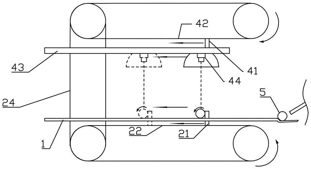
[0022] Embodiment 1: as figure 1 The workpiece inspection device shown includes a frame, a flat plate 1, a pusher for pushing a cylindrical workpiece 5 to roll on the flat plate, a camera above the flat plate 1, and a camera transporter for pushing the camera. The flat plate 1 is inclined. The push piece includes a workpiece conveyor belt 22 and a push plate 21, the flat plate 1 has a long hole, and the push plate 21 is located below the flat plate 1 and extends into the long hole;

[0023] The camera transport part comprises a track 43 and a camera conveyor belt 42 fixed on the frame, the camera 44 is slidably connected to the track 43, the track 43 is fixed on the frame, a return spring is provided between the camera 44 and the track 43, and the camera conveyor belt 42 A camera push plate 41 is fixed, and the camera push plate 41 stretches between the tracks to resist the camera 44, and the camera push plate 41 and the push plate 21 move in the same direction and at the sam...

Embodiment 2

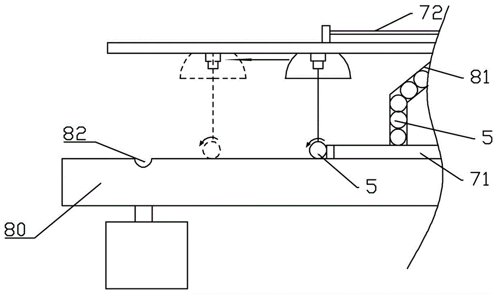
[0025] Embodiment 2: as figure 2 As shown, the difference between Embodiment 2 and Embodiment 1 is that the camera transport part is connected with a camera pushing stepping motor, and the camera pushing stepping motor has a camera push rod 72, and the pushing part is connected with a workpiece pushing stepping motor, and the workpiece pushing stepping motor A workpiece push rod 71 is provided. The flat plate 80 is provided with a feed pipe 81 and a discharge chute 82 .

Embodiment 3

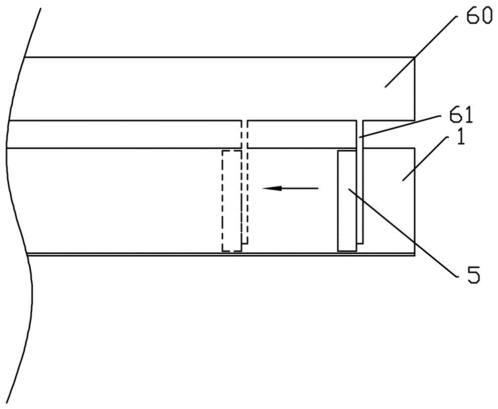
[0026] Embodiment 3: as image 3 As shown, the difference between Embodiment 3 and Embodiment 2 is that the push piece includes a workpiece conveyor belt 60 and a push plate 61, the push plate 61 is fixed on the workpiece conveyor belt, and the push plate 61 is located on one side of the workpiece.


PUM


Abstract

The invention relates to a workpiece image detection device, in particular to a workpiece inspection device. The workpiece inspection device comprises a machine frame, a flat plate, a pushing part for pushing a cylindrical workpiece to roll on the flat plate and a shooting mechanism; the shooting mechanism comprises a camera for shooting the cylindrical workpiece. The workpiece inspection device is characterized by further comprising a camera transporting part for pushing the camera; the camera transporting part is fixedly connected with the camera and is positioned above the flat plate, the speed of the camera transporting part is equal to that of the pushing part, the moving direction of the camera transporting part is parallel to and the same as that of the pushing part. The invention aims to provide a high-precision automatic detection device for the cylindrical workpiece.

Description

technical field [0001] The invention relates to a workpiece image detection device, in particular to a workpiece inspection device. Background technique [0002] In the parts processing industry, it is necessary to check whether the parts meet the standards before they leave the factory. With the development of image recognition technology, the automatic parts inspection technology is becoming more and more mature, and the inspection speed and inspection accuracy are higher than manual inspection. More and more of companies use image recognition technology to inspect workpieces. [0003] When using image recognition technology to detect workpieces, generally speaking, at least six sides of the workpiece must be photographed, and then the photographed images should be inspected. Therefore, image recognition needs to collect the surface information of the part from multiple angles, which means that multiple cameras need to be set up to shoot the workpiece from multiple angles...

Claims


Application Information

Patent Timeline
Patent Type & Authority Applications(China)
IPC IPC(8): G01N21/89
CPCG01N21/8901
Inventor 王全中
Owner CHONGQING SUTENG MACHINERY MFG
Why Eureka
Try Eureka