
A low-impedance contact conductive test electrode

A test electrode, low impedance technology, applied in the field of testing, can solve problems such as poor electrical connection performance, and achieve the effect of ensuring overcurrent capability, test effect and test efficiency.

Active Publication Date: 2019-07-23
REPOWER TECH CO LTD
View PDF8 Cites 0 Cited by
  • Summary
  • Abstract
  • Description
  • Claims
  • Application Information

AI Technical Summary

Problems solved by technology

[0003] The purpose of the present invention is to provide a low-impedance contact conductive test electrode, which aims to solve the problem of poor electrical connection performance caused by the contact conductive test electrode in the prior art due to continuous movement due to crimping with the electrical component under test

Method used


Image

  • A low-impedance contact conductive test electrode
  • A low-impedance contact conductive test electrode
  • A low-impedance contact conductive test electrode

Examples


Embodiment Construction

[0022] In order to make the object, technical solution and advantages of the present invention clearer, the present invention will be further described in detail below in conjunction with the accompanying drawings and embodiments. It should be understood that the specific embodiments described here are only used to explain the present invention, not to limit the present invention.

[0023] It should be noted that when an element is referred to as being “fixed on” or “disposed on” another element, it may be directly on the other element or there may be an intervening element at the same time. When an element is referred to as being "connected to" another element, it can be directly connected to the other element or intervening elements may also be present.

[0024] It should also be noted that the orientation terms such as left, right, up, and down in this embodiment are only relative concepts or refer to the normal use state of the product, and should not be regarded as limiti...


PUM


Abstract

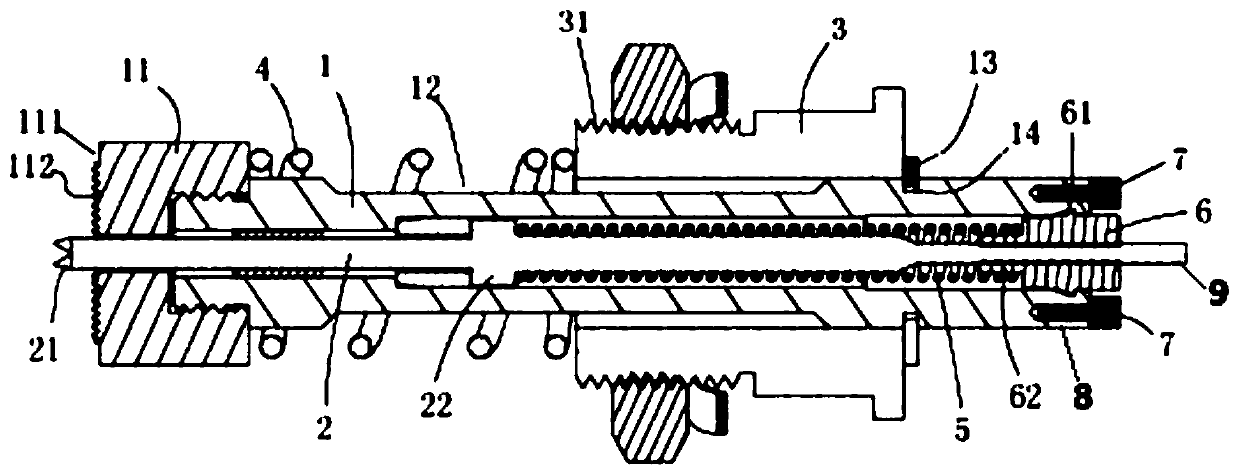
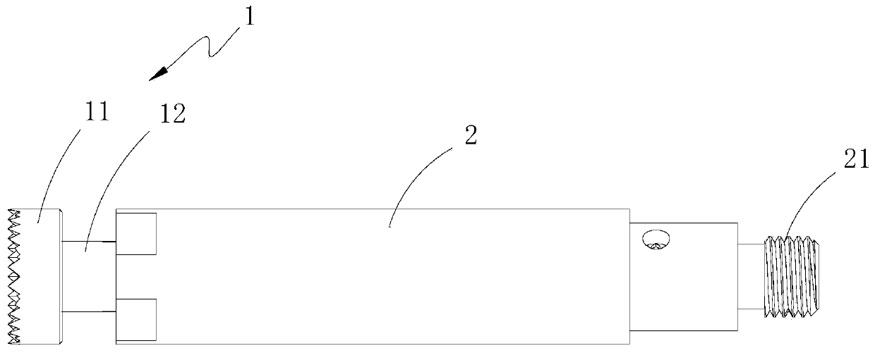
The invention is suitable for the technical field of test and provides a low-impedance contact conductive test electrode. A sleeve provided with an accommodation cavity is sleeved on a pin rod of a probe, a first spring is abutted between the side wall of the pin rod of the probe and the side wall of the accommodation cavity of the sleeve, a second spring is abutted between the tail end of the probe and the closed end of the accommodation cavity, and the pin rod of the probe is provided with an anti-drop device to prevent the probe from dropping from the sleeve, so that when the probe makes contact with and is pressed by an electrical element under test, the probe and the sleeve can be still in good electric connection even if the axial deviation and angle deviation occur, discharge capacity of the electrical signal is ensured, and test effect and test efficiency are guaranteed.

Description

technical field [0001] The invention belongs to the technical field of testing, in particular to a low-impedance contact conductive testing electrode. Background technique [0002] When the contact conductive test electrode is crimped with the electrical component under test, springs are generally used for buffering and angle adjustment to make the connection tighter. The spring is generally arranged on the outside of the conductive device. For example, the Chinese patent No. CN201510537634 belongs to this situation, such as figure 1 As shown, the compression spring (4) is fixed on the outside of the conductive device to play a buffering role. The probe is fixed to the test bench through the sleeve (3), because the test bench will be firmly fixed on the ground, that is to say the sleeve (3) is motionless relative to the ground. When the probe probe (11) is connected to the electrical component under test, there will be pressure to the right, but the sleeve (3) will not mov...

Claims


Application Information

Patent Timeline
Patent Type & Authority Patents(China)
IPC IPC(8): G01R1/067
CPCG01R1/06711
Inventor 毛广甫
Owner REPOWER TECH CO LTD
Learn More