
Modularized electronic-technique comprehensive application experimental box

A technology of electronic technology and experimental box, which is applied in the field of electronic technology teaching experimental equipment, can solve problems such as insufficient design and comprehensive experiments, failure to reflect circuit correlation, and insufficient experimental modules, so as to facilitate development and supplement and function upgrades Easy, lab-space-saving effect

Inactive Publication Date: 2017-05-24
COMMUNICATION UNIVERSITY OF CHINA
View PDF4 Cites 8 Cited by
  • Summary
  • Abstract
  • Description
  • Claims
  • Application Information

AI Technical Summary

Problems solved by technology

[0002] Electronic technology experiments are an important part of the practical teaching of electronic subjects. Experimental courses are inseparable from various experimental devices and experimental boxes. However, they are currently widely used in various electronic circuit experiments in the practical teaching of electronic courses in colleges and universities. All of these boxes have single functions to varying degrees, and insufficient design and comprehensive experiments. Although the experimental content is modular, the module functions are independent and cannot reflect the correlation between circuits; some experimental boxes adopt open designs, such as too many The placement of breadboards and chip holders makes the experimental content setting unruly; some experimental content is too restricted, the experimental modules are not rich enough, and cannot be flexibly expanded, etc.

Method used


Image

  • Modularized electronic-technique comprehensive application experimental box
  • Modularized electronic-technique comprehensive application experimental box

Examples


Embodiment Construction

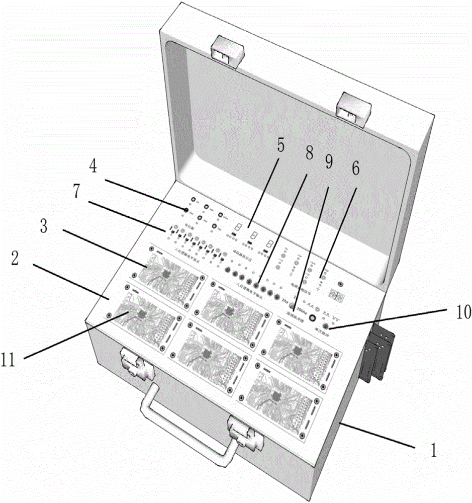
[0025] Such as figure 1 As shown, the experimental box for the comprehensive application of modular electronic technology includes a box body 1, a base plate 2 installed on the box body 1, and an experimental expansion board 3; the base plate 2 and the box body 1 are connected by two hinges near the box cover. The base plate is divided into two parts: the auxiliary function area and the experimental module installation area. From left to right, the first layer of the auxiliary function area is the variable resistance area 4, the decoder display area 5, the power output area, and the audio signal input and output area 6. The second layer of the auxiliary function area is, from left to right, a logic level test area 7, a logic level output area 8, a continuously adjustable pulse signal 9, and a single pulse signal generator 10. The experimental module installation area is divided into six experimental expansion areas, and the experimental expansion board 3 is installed. The bu...


PUM


Abstract

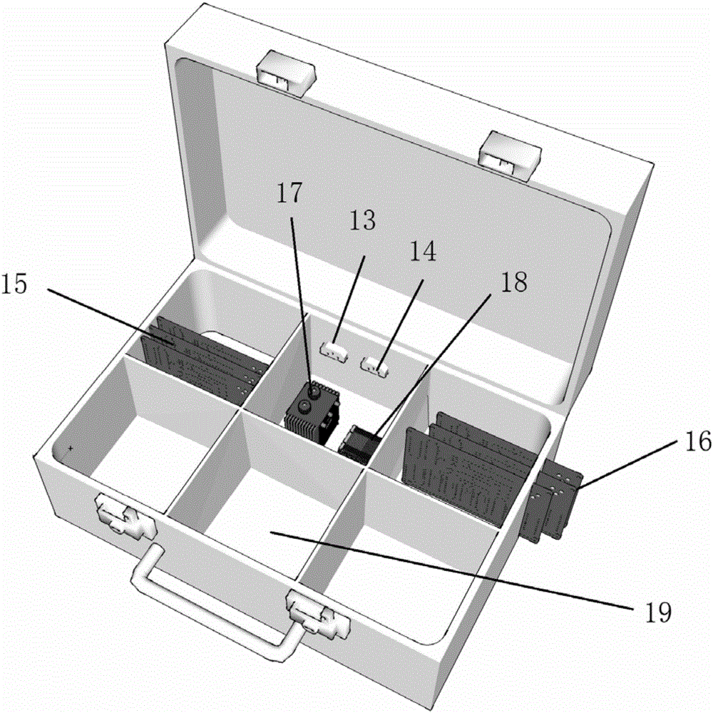
The invention discloses a modularized electronic-technique comprehensive application experimental box, and relates to the field of electronic-technique teaching facilities. The modularized electronic-technique comprehensive application experimental box is characterized by comprising a functionalized box body, a base plate and an experimental functional module plate, wherein the base plate is mounted on the box body. The base plate is divided into two parts of an auxiliary functional area and an experimental module mounting area. A power supply application module, a pulse signal generator, a decoding display module, a logic level measuring module, a logic level output module, an audio signal input-output module, a single-turn potentiometer, a multi-turn potentiometer and the like are integrated in the auxiliary functional area. A bus connecting way is adopted for the experimental module mounting area; independent experimental units are mounted in experimental expansion areas respectively in a module form by using copper banana plugs; an experimental plate is provided with six experimental modules at the same time; the modules can be interconnected and intercommunicated through buses. Each experimental plate can be used for independently carrying out an experiment and a test on the base plate, and is plugged back into the box body to form a system with rest templates; a system function in some aspect is completed. The middle of the box body is used for storing experimental expansion plates which are nested and piled together.

Description

technical field [0001] The invention relates to the field of electronic technology teaching experimental equipment, in particular to an experimental equipment for the comprehensive application of analog electronic technology and digital electronic technology. Background technique [0002] Electronic technology experiments are an important part of the practical teaching of electronic subjects. Experimental courses are inseparable from various experimental devices and experimental boxes. However, they are currently widely used in various electronic circuit experiments in the practical teaching of electronic courses in colleges and universities. All of these boxes have single functions to varying degrees, and insufficient design and comprehensive experiments. Although the experimental content is modular, the module functions are independent and cannot reflect the correlation between circuits; some experimental boxes adopt open designs, such as too many The placement of breadboa...

Claims


Application Information

Patent Timeline
IPC IPC(8): G09B23/18
CPCG09B23/185
Inventor 赵宇鲍南海于鹏王楠章文辉
Owner COMMUNICATION UNIVERSITY OF CHINA
Learn More