Novel power cable joint box

A technology for power cables and splice boxes, applied to cable joints, instruments, measuring devices, etc., can solve problems such as inability to protect cables, poor waterproof performance, affect the performance and scope of application of cable splice boxes, and achieve effective protection and good waterproofing performance effect

Inactive Publication Date: 2017-05-24
成都聚立汇信科技有限公司
View PDF6 Cites 6 Cited by
  • Summary
  • Abstract
  • Description
  • Claims
  • Application Information

AI Technical Summary

Problems solved by technology

However, for the existing cable joint box, limited by the structural and design constraints, it still cannot fully protect the cable during use, such as the cable is likely to be broken, and its waterproof performance

Method used


Image

  • Novel power cable joint box

Examples


Embodiment Construction

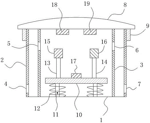
[0013] Such as figure 1 As shown, a new type of power cable splice box includes a cylindrical box body 1, the vertical side wall of the box body 1 is a double-layer structure including an outer layer body 2 and an inner layer body 3, and the outer layer body 2 The lower left side is also provided with an outer wire inlet 4, and the upper left side of the inner layer body 3 is also provided with an inner wire inlet 5, and the upper right side of the inner layer body 3 is also provided with an inner wire outlet hole 6. The lower part of the right side of 2 is also provided with an external wire hole 7, and an external thread is also provided on the top of the outer layer body 2, so that external rainwater, etc. can be effectively prevented from entering the inside of the box body 1 through each wire inlet hole and wire outlet hole; The top of the box body 1 is also provided with a cover body 8, and the bottom end of the cover body 8 is also provided with an annular plate 9 exten...


PUM


Abstract

The invention relates to a novel power cable joint box, and the box comprises a box body. A vertical side wall of the box body comprises an outer layer and an inner layer. The lower part of the left side of the outer layer and the upper part of the left side of the inner layer are respectively provided with an outer wire incoming hole and an inner wire incoming hole. The upper part of the right side of the inner layer and the lower part of the right side of the outer layer are respectively provided with an inner wire outgoing hole and an outer wire outgoing hole. The top of the outer layer is provided with an outer thread, and the top of the box body is provided with a cover body. The bottom of the cover body is provided with an annular plate, and the inner surface of the annular plate is provided with an inner thread in thread fit with the outer thread. The interior of the box body is provided with a supporting plate, and a telescoping rod and a spiral damping spring are connected between the supporting plate and the bottom wall of the box body. The supporting plate is provided with a left insulating supporting rod and a right insulating supporting rod, and the top of the left insulating supporting rod and the top of the right insulating supporting rod are respectively provided with a left cable fixing clamp and a right cable fixing clamp. The supporting plate is provided with a vibration sensor, and the bottom of the cover body is provided with a microcontroller, an alarm, and a wireless emitter. Through the above structure, the box is better in waterproof performance, and can achieve the more effective protection of a cable.

Description

technical field [0001] The invention relates to a novel power cable joint box. Background technique [0002] During the laying of power cables, cable splice boxes are often used. As an important part used to connect two or more cables together and provide protection, the quality and performance of the cable joint box directly affect the quality and service life of the power cable. However, for the existing cable joint box, limited by the structural and design constraints, it still cannot fully protect the cable during use, such as the cable is likely to be broken, and its waterproof performance is also poor. It is easy to cause external rainwater to enter the interior of the cable joint box and cause corrosion to the cables and cable joints, which greatly affects the performance and scope of application of the cable joint box. Contents of the invention [0003] In order to overcome the above deficiencies in the prior art, the technical problem to be solved by the present...

Claims


Application Information

Patent Timeline
IPC IPC(8): H02G15/10G01D21/02
CPCH02G15/10G01D21/02
Inventor 吕静
Owner 成都聚立汇信科技有限公司
Why Eureka
Try Eureka