Method and device for joining a composite sheet metal component to another component

A technology of components and composites, applied in welding monitoring devices, welding equipment, welding power supplies, etc., to achieve the effects of reducing wear, fast cost, and improving takt time

Active Publication Date: 2017-05-24
VOLKSWAGEN AG
View PDF8 Cites 3 Cited by
  • Summary
  • Abstract
  • Description
  • Claims
  • Application Information

AI Technical Summary

Problems solved by technology

Joining methods for connecting composite panel members with functional elements (e.g. connectors such as studs and nuts) are not known in the prior art

Method used


Image

  • Method and device for joining a composite sheet metal component to another component
  • Method and device for joining a composite sheet metal component to another component
  • Method and device for joining a composite sheet metal component to another component

Examples


Embodiment Construction

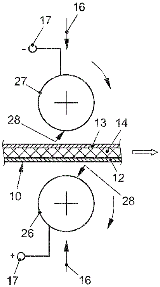
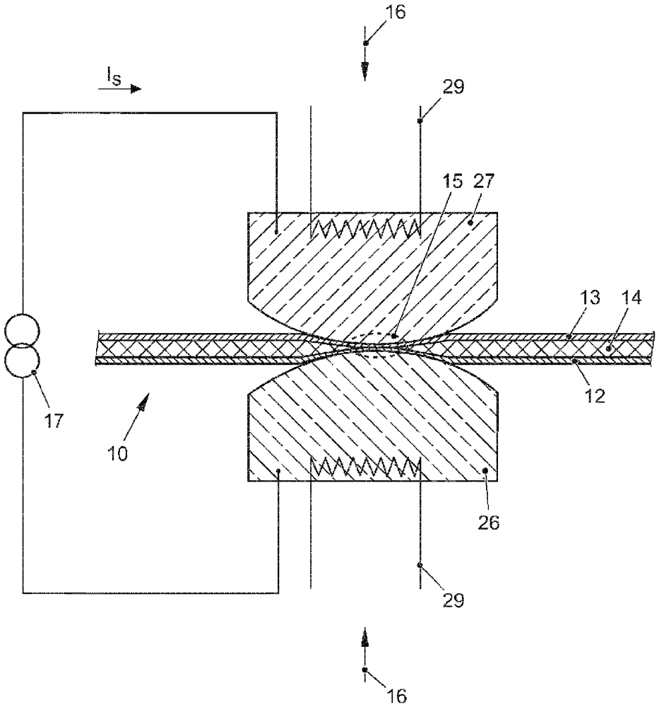
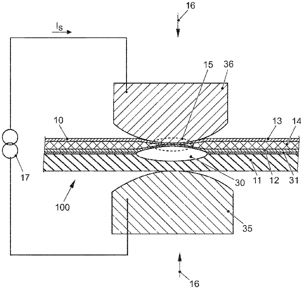
[0053] Figure 1a Method steps a) to c) for preparing the joining point 15 on the first component 10 are shown. The first component 10 is multi-layered and has two plate-like structural elements 12 , 13 and an intermediate layer 14 arranged between the two structural elements 12 , 13 . The intermediate layer is designed as a layer with plastic. In order to connect the first member 10 and the second member 11 (in Figure 1a not shown in ), the joining method must be arranged such that the joining site 15 is prepared before the first member 10 and the second member 11 are connected. It is important here that the intermediate layer 14 is pressed in the region of the joining point 15 so that a contact is produced in this region between the two structural elements 12 , 13 .

[0054] The pressing means 26 , 27 for applying pressure in step b) can be, for example, electrode caps of a welding device. Furthermore, different tools can be used for the individual method steps a) to c). ...


PUM


Abstract

The aim of the invention is to improve a method for joining a multilayer component to another component such that the joining method and the preparation of the joint locations can be carried out as quickly as possible and inexpensively using an automatic method. This is achieved in that an intermediate layer (14) of the multilayer component is displaced in the region of the joint location (15) by means of a heating process and by exerting a compressive force (16), and the two outer components (10, 11) of the multilayer component are adhered together by applying an electric voltage (17).

Description

technical field [0001] The invention relates to a method for joining a first component and a second component at a joint point of the first component, wherein the first component has at least one first substantially planar structural element, a substantially planar The formed second structural element and the intermediate layer comprising plastic is arranged at least in sections between the two structural elements. [0002] Furthermore, the invention relates to a structural element complex comprising a first component and a second component connected to the first component at a junction point of the first component. [0003] Furthermore, the invention relates to a device for joint site preparation of a joint site at a first component for joining a first component with a second component at a joint site of the first component. Background technique [0004] Lightweight constructions based, for example, on aluminum or composite sheet components are known in automobile construc...

Claims


Application Information

Patent Timeline
Patent Type & Authority Applications(China)
IPC IPC(8): B23K9/20B23K9/235B23K11/06B23K11/11B23K11/16B23K11/25B23K11/30B23K11/34B23K103/16
CPCB23K9/0035B23K9/20B23K9/235B23K11/0053B23K11/06B23K11/115B23K11/163B23K11/253B23K11/258B23K11/3018B23K11/3045B23K11/34B23K2103/172
Inventor A.福伊格特
Owner VOLKSWAGEN AG
Why Eureka
Try Eureka