An anti-bird device for power transmission towers
A transmission pole tower, anti-bird technology, applied in the direction of towers, building types, buildings, etc., can solve the problems of cumbersome structure, inability to achieve bird repelling effect, and achieve good bird repelling effect
- Summary
- Abstract
- Description
- Claims
- Application Information
AI Technical Summary
Problems solved by technology
Method used
Image
Examples
Embodiment 1
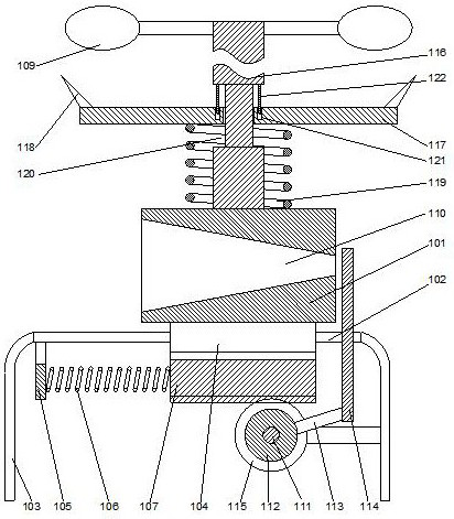
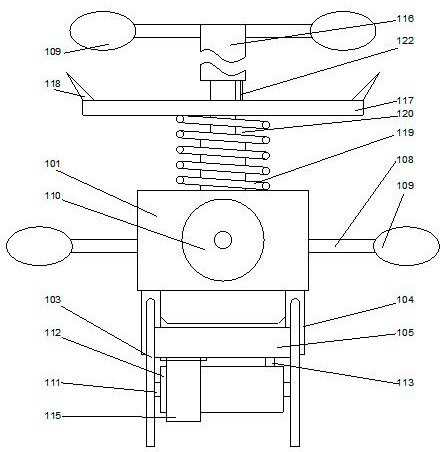
[0024] In this embodiment, in order to prevent birds from standing on the upper end surface of the base, preferably, a column 116 is arranged on the upper end surface of the base 101, so that the column is perpendicular to the plane where the upper end surface of the base is located, and the column 116 is far away from the One end of the base 101 is fitted with a blade 109 . The blades are rotated and connected to the columns, and under the action of wind force, the blades are rotated around the columns to prevent birds from standing on the upper end surface of the base.
Embodiment 2
[0026] In this embodiment, on the basis of Embodiment 1, in order to avoid birds standing between the base and the blades on the column, preferably, a turntable 117 is provided at the end of the column 116 close to the base 101, so that the turntable It is a hollow ring structure, so that the middle part of the turntable 117 is set on the upright 116 and can rotate relative to the upright. A sharp part 118 is provided on the edge of the turntable 117 to prevent birds from standing on the edge of the turntable. The base 101 is provided with a compression spring 119, so that the inner diameter of the compression spring is larger than the outer diameter of the column, so that the compression spring 119 is sleeved on the outside of the column 116, and the end of the compression spring 119 away from the base 101 fits On the lower surface of the turntable 117, when the bird stands on the turntable, the turntable will move down under the action of gravity, and the turntable will squee...
Embodiment 3
[0028] In this embodiment, on the basis of Embodiment 2, in order to facilitate the installation of the turntable, preferably, an annular groove 120 is provided on the column 116, so that the annular groove is located in the middle of the column, and the middle of the turntable 117 Set on the annular groove 120, so that the inner diameter of the turntable is larger than the outer diameter of the annular groove, and smaller than the outer diameter of the column, the turntable can move longitudinally inside the annular groove, which can facilitate the installation of the turntable and improve the The stability of the turntable.
[0029] In this embodiment, further preferably, a positioning groove 121 is provided on the upper end surface of the turntable 117, the positioning groove is centered on the axis of the turntable, and its longitudinal projection is in an arc-shaped structure, and the depth of the positioning groove 121 is gradually The increased arc-shaped half-through g...
PUM
 Abstract
Description
Claims
Application Information
 - R&D
- Intellectual Property
- Life Sciences
- Materials
- Tech Scout
- Unparalleled Data Quality
- Higher Quality Content
- 60% Fewer Hallucinations
Browse by: Latest US Patents, China's latest patents, Technical Efficacy Thesaurus, Application Domain, Technology Topic, Popular Technical Reports.
© 2025 PatSnap. All rights reserved.Legal|Privacy policy|Modern Slavery Act Transparency Statement|Sitemap|About US| Contact US: help@patsnap.com


