Multiple type hemostasis clip application clamp

A hemostatic clip and clamp applicator technology, applied in the field of medical supplies, can solve problems such as difficult advance and reset, insufficient power, difficult processing, etc., and achieve the effects of simplifying parts, improving closure strength, and convenient use

Inactive Publication Date: 2017-05-31
CHENGDU IDING IND PROD DESIGN
View PDF7 Cites 0 Cited by
  • Summary
  • Abstract
  • Description
  • Claims
  • Application Information

AI Technical Summary

Problems solved by technology

[0005] Although the above-mentioned clip applier effectively improves the bursting effect of the clip applier, there is a problem of insufficient bite force of the clip applier during use, and at the same time, the clip is easy to bend and insufficient in strength. As a result, the power is insufficient when pushing, and it is difficult for the hemostatic clip to advance smoothly to the designated position, such as figure 1 , with figure 2 , and at the same time, if high-strength materials such as metal are used for processing, since the limit strip on the clip and the clip are integrally formed, if high-strength materials are used for processing, on the one hand, it is difficult to process, and on the other hand, the one-piece molding leads to The limit bar is not elastic enough, it is difficult to advance and reset effectively,

Method used


Image

  • Multiple type hemostasis clip application clamp
  • Multiple type hemostasis clip application clamp
  • Multiple type hemostasis clip application clamp

Examples


Embodiment 1

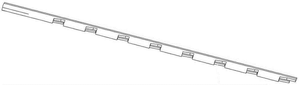
[0040] Embodiment 1: Embodiment 1 is a kind of clip 1, as Figure 7 As shown, this kind of clip is made of iron. This kind of clip includes a sheet-shaped clip body 101. The clip body 101 is provided with nine push clips 102. The push clip is also a sheet-shaped structure. The middle of the piece is a curved or bent structure, and the push clip is fixedly connected with the clip body rivet 104. The length of the front push clip can be determined according to the positional relationship between the pliers head and the clip. Hook 103

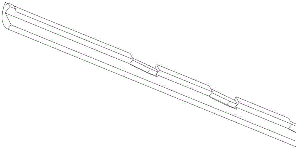
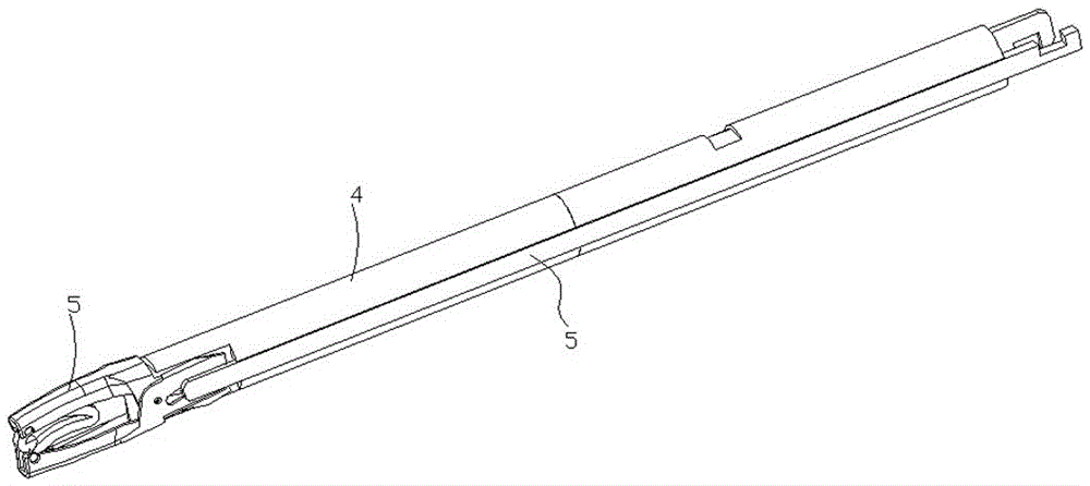
[0041] On the basis of the above-mentioned clip 1, it can be used in conjunction with a clamp applicator, including a pincer head 6 and a pincer tube. The length is shorter than the lumen 4, and the exposed part of the lumen is covered by the tailpipe when in use (not shown in the figure). One end of the lumen 4 near the forceps head is provided with a rotating table 401 and a movable table 402, the rotating table is provided with a rotating hol...

Embodiment 2

[0044] Embodiment 2: In embodiment 2, the clips and clips used are the same as in embodiment 1, but the existing clips and clips can also be used. In embodiment 2, the lower jaw 602 and the tube Cavity 4 is designed to be fixedly connected, and can be integrally formed, such as Figure 9 Said, that is, the lumen 4 and the lower jaw 602 are one part, and the side of the lumen 4 also has a turning hole 406, and the upper jaw 601 can rotate around the turning hole 602 to form the opening and closing of the pliers head. The tube in embodiment 2 The cavity is not absolutely integrally formed, it can also be divided into several parts and then connected. A specific connection method can be punched on several parts, and then connected to the pipe sleeve by rivets or other conventional methods. That is to say, a concave platform 404 can also be provided on the lumen, and the concave platform can be linked with the power device.

[0045] Compared with the linkage 5 in Example 1, other...


PUM


Abstract

The invention discloses a multiple type hemostasis clip application clamp, and belongs to the field of medical consumables. The using effect of the multiple type hemostasis clip application clamp is improved. The multiple type hemostasis clip application clamp comprises a clamp head (6) and a clamp tube. A linkage piece (5) is arranged inside the clamp tube. The clamp head comprises an upper jaw (601) and a lower jaw (602). One of the upper jaw and the lower jaw penetrates into the clamp tube, the other one of the upper jaw and the lower jaw is connected with the linkage piece (5), and the upper jaw and the lower jaw form a rotating device.

Description

technical field [0001] The invention relates to the field of medical supplies, in particular to a hemostatic clip applicator. Background technique [0002] Hemostatic clip applicator is a medical consumable widely used in surgery, and has great application value in surgery, especially in the field of minimally invasive surgery. [0003] The current existing surgical clip appliers are mainly divided into single-shot and multi-shot. Among them, the single-shot type needs to be reinstalled with a new hemostatic clip after each hemostatic clip is finished, while the multi-shot type needs to be reinstalled after each hemostatic clip is applied. There are multiple hemostatic clips loaded in the device, but the current multi-shot hemostatic clip applier is inconvenient to use, prone to accidents during use, insufficient hemostatic clip fastening, insufficient accuracy, and incoherent use. [0004] The application number is 201610544232.2, and the invention patent titled a hemostat...

Claims


Application Information

Patent Timeline
Patent Type & Authority Applications(China)
IPC IPC(8): A61B17/128
CPCA61B17/1285A61B2017/12004
Inventor 张文俊
Owner CHENGDU IDING IND PROD DESIGN
Why Eureka
Try Eureka