
Medical cooling cap with cold air hole

A technology of cold air and cap body, applied in the field of clinical medical equipment, can solve the problems of poor cooling effect, failure to avoid cold therapy, poor patient comfort, etc., and achieve the effect of novel overall structure, wide application prospect and unique design

Pending Publication Date: 2017-05-31
LUOYANG CENT HOSPITAL
View PDF9 Cites 5 Cited by
  • Summary
  • Abstract
  • Description
  • Claims
  • Application Information

AI Technical Summary

Problems solved by technology

[0004] First, in the design, all adopt blunt and rapid cooling to achieve the purpose of treatment, but do not consider the side effects, and do not avoid the taboo parts of cold therapy, such as the posterior occiput and auricle, which are prone to adverse complications of cold therapy;
[0005] Second, the cap body is all hard and cannot be bent at will to make close contact with the patient's head. The patient's comfort is poor. Wearing it for a long time is likely to cause adverse complications such as pressure sores, and the cooling effect is not good;
[0006] Its three, easily produce condensed water in use, soak the articles such as towel and pillow, sheet etc. that are wrapped in the head, be unfavorable for patient's nursing, simultaneously, when changing these articles, frequently move the patient's head, will There is a possibility of aggravating the condition;
[0007] Fourth, poor fixation, easy to slip;
[0008] Fifth, if the ice cubes in the ice cap melt quickly, items such as towels soaked in condensed water and large towels covering the ice cap need to be replaced frequently. At the same time, it is necessary to frequently check whether the patient's ears and occipital are frostbitten. phenomenon, the workload of nurses is quite heavy

Method used


Image

  • Medical cooling cap with cold air hole
  • Medical cooling cap with cold air hole
  • Medical cooling cap with cold air hole

Examples


Embodiment Construction

[0033] The specific implementation mode is given below in conjunction with the accompanying drawings, and the technical solution of the present invention is further described in detail.

[0034] The embodiments provided below are the best embodiments given on the premise of the above-mentioned technical solution of the present invention, and are for reference only, and the specific implementation conditions shall be combined with the actual operations of those skilled in the art.

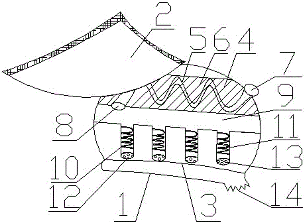
[0035] Such as Figure 1-4 As shown, a medical cooling cap with cold air holes includes a cap body 1 and an air inlet 7 arranged on the cap body 1, the cap body 1 includes an outer layer 2 and an inner layer 3, and the outer layer 2 and the inner layer An intermediate interlayer is formed between the inner layers 3, and an independent cold source chamber 4 and a cold air chamber 9 located below the cold source chamber 4 are arranged in the intermediate interlayer. Type pipe 5, one port of S-type pi...


PUM


Abstract

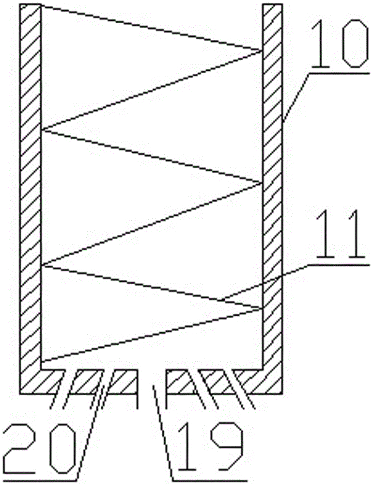
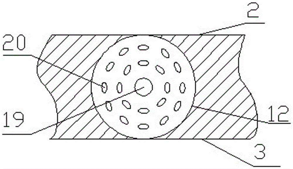
The invention provides a medical cooling cap with a cold air hole. The cap comprises a cap body and an air inlet formed in the cap body. The cap body comprises an outer layer and an inner layer, a middle interlayer is formed between the outer layer and the inner layer, and a cold source cavity and a cold air cavity are arranged in the middle interlayer. The cold source cavity is internally provided with an S-type pipe extending in the width direction of the cap body, and the outer pipe wall of the S-type pipe is covered with a cold source medium used for changing normal air into cold air. A buffering pipe comprises a pipe body, a spiral groove and a damping plate, wherein the spiral groove and the damping plate are used for buffering airflows. A plurality of cold air holes are evenly distributed in the damping plate. The cold air holes are composed of a straight hole exactly under the middle of the spiral groove and a plurality of inclined holes distributed around the straight hole in the circumferential direction. The cap is novel as a whole, unique in structure, different from existing cooling caps, and capable of performing good cooling therapy and also protecting the skin due to close matching of multi-level parts and continuous buffering and cooling.

Description

technical field [0001] The invention belongs to the field of clinical medical appliances, in particular to a medical cooling cap with cold air holes. Background technique [0002] For patients with cerebral hemorrhage, cerebral edema, encephalitis, intracranial hypertension, traumatic brain injury, febrile convulsions and central hyperthermia, the cooling effect of drugs is not good. Clinically, physical cooling of the head or mild hypothermia are generally used for treatment. This treatment generally requires long-term use of a brain cooling device, that is, cooling the head of the human body through an ice cap or the like. On the other hand, the most common complication of using a craniocerebral cooling device is skin frostbite. To prevent frostbite, a towel is often used to wrap the patient's head and ears clinically. The chances of frostbite are greatly increased. [0003] At present, most of the existing general-purpose cooling instruments are blankets and caps, which...

Claims


Application Information

Patent Timeline
IPC IPC(8): A61F7/00
CPCA61F7/00A61F2007/0064A61F2007/0002
Inventor 张英英靳胜燕
Owner LUOYANG CENT HOSPITAL
Learn More