Fire-fighting equipment and control system and method thereof

A fire-fighting equipment and control system technology, which is applied in fire rescue and other directions, can solve problems such as loss of personnel and property, delay of fire-fighting timing, waste of water resources and foam resources, etc., and achieve the effect of improving fire-fighting efficiency and reducing loss of personnel and property

Inactive Publication Date: 2017-05-31
SANY AUTOMOBILE MFG CO LTD
View PDF8 Cites 6 Cited by
  • Summary
  • Abstract
  • Description
  • Claims
  • Application Information

AI Technical Summary

Problems solved by technology

[0002] At present, in fire rescue, due to the interference of dense smoke, etc., the environment of the fire scene cannot be clearly perceived visually, and firefighters generally cannot accurately determine the location of the fire point, let alone quickly extinguish the fire at the fire point, especially compared to the current long-arm As far as the fire truck is concerned, the firefighters on the ground are not only unable to accurately determine the location of the fire point, but sometimes they cannot even accurately understand the position of the fire truck nozzle (water cannon)
On the one hand, it causes waste of water resources and foam resources; on the other hand, it delays the timing of fire extinguishing and causes greater loss of personnel and property.

Method used


Image

  • Fire-fighting equipment and control system and method thereof
  • Fire-fighting equipment and control system and method thereof
  • Fire-fighting equipment and control system and method thereof

Examples


Embodiment Construction

[0038] It should be noted that, in the case of no conflict, the embodiments of the present invention and the features in the embodiments can be combined with each other. In order to describe the control system and method of the fire fighting equipment of the present invention in detail, the present invention will be described in detail below with reference to the accompanying drawings and in conjunction with the embodiments.

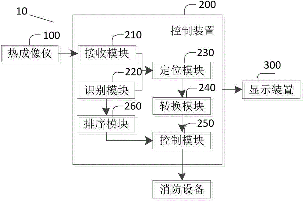
[0039] Such as figure 1 As shown, a preferred embodiment of the control system of the fire fighting equipment of the present invention is shown. Specifically, the control system includes: a thermal imager 100 and a control device 200 . Wherein, the thermal imager 100 is set on the fire fighting equipment, and is used to obtain the thermal map of the fire area in real time. The control device 200 is connected with the thermal imager 100 and is used for identifying the ignition point of the fire area according to the above thermal map.

[0040] In this ...


PUM


Abstract

The invention discloses fire-fighting equipment and a control system and method thereof. The system comprises a thermal imager and a control device, wherein the thermal imager is arranged on the fire-fighting equipment and used for obtaining a thermodynamic diagram of a fire zone in real time; and the control device is connected with the thermal imager and used for recognizing a fire point of the fire zone according to the thermodynamic diagram. By means of the system and the corresponding method, the thermodynamic diagram of the fire zone can be obtained in real time through the thermal imager according to the thermal imaging principle and sent to the control device, the fire point of the fire zone can be recognized by the control device according to the thermodynamic diagram so as to provide reference for firefighters, and therefore the firefighters can effectively know the information of a fire scene according to the reference information, control a jet orifice of the fire-fighting equipment to move to the fire point, and carry out fixed-point fire extinguishing on the fire point. Thus, the utilization rate of water resources and foam resources can be increased, moreover, fire extinguishing efficiency can be improved, and personnel and property loss is reduced to the maximum extent.

Description

technical field [0001] The invention relates to the control technology of fire-fighting equipment, in particular to a fire-fighting equipment and its control system and method. Background technique [0002] At present, in fire rescue, due to the interference of dense smoke, etc., the environment of the fire scene cannot be clearly perceived visually, and firefighters generally cannot accurately determine the location of the fire point, let alone quickly extinguish the fire at the fire point, especially compared to the current long-arm As far as the fire truck is concerned, the firefighters on the ground are not only unable to accurately determine the location of the fire point, but sometimes they cannot even accurately understand the position of the fire truck nozzle (water cannon). On the one hand, it causes waste of water resources and foam resources; on the other hand, it delays the timing of fire extinguishing and causes greater loss of personnel and property. [0003] ...

Claims


Application Information

Patent Timeline
Patent Type & Authority Applications(China)
IPC IPC(8): A62C37/00A62C27/00
CPCA62C37/00A62C27/00
Inventor 蒲东亮彭阳辉郑丽文张亮
Owner SANY AUTOMOBILE MFG CO LTD
Why Eureka
Try Eureka