Sluice valve capable of automatically detecting water velocity in real time

A technology of real-time detection and water flow speed, applied in the direction of sliding valve, valve details, valve device, etc., can solve the problem of inability to know the status, and achieve the effect of ingenious design, long life, convenient disassembly and assembly

Active Publication Date: 2018-10-16
温州市斯罗登阀门配件有限公司
View PDF6 Cites 2 Cited by
  • Summary
  • Abstract
  • Description
  • Claims
  • Application Information

AI Technical Summary

Problems solved by technology

[0003] The gate valve is a device that can cut off the water flow at any time. Generally, the gate valve is installed in the middle of the pipeline. The staff can control the gate valve at any time to decide whether the water flow needs to be cut off. The pipeline that needs to cut off the water flow generally has strict water control. However, because the gate valve is a closed structure, the internal situation can only be controlled through the external structure, and the staff cannot know the internal situation, but often the pipelines that need to control the water flow often need to know the data such as water speed and flow. But these data can only be understood through other external equipment measurement

Method used


Image

  • Sluice valve capable of automatically detecting water velocity in real time
  • Sluice valve capable of automatically detecting water velocity in real time
  • Sluice valve capable of automatically detecting water velocity in real time

Examples


Embodiment Construction

[0028] The specific implementation manners of the present invention will be further described in detail below in conjunction with the accompanying drawings and embodiments. The following examples are used to illustrate the present invention, but are not intended to limit the scope of the present invention.

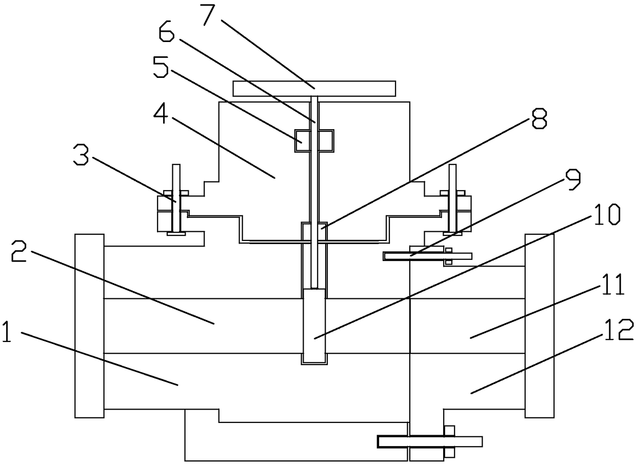
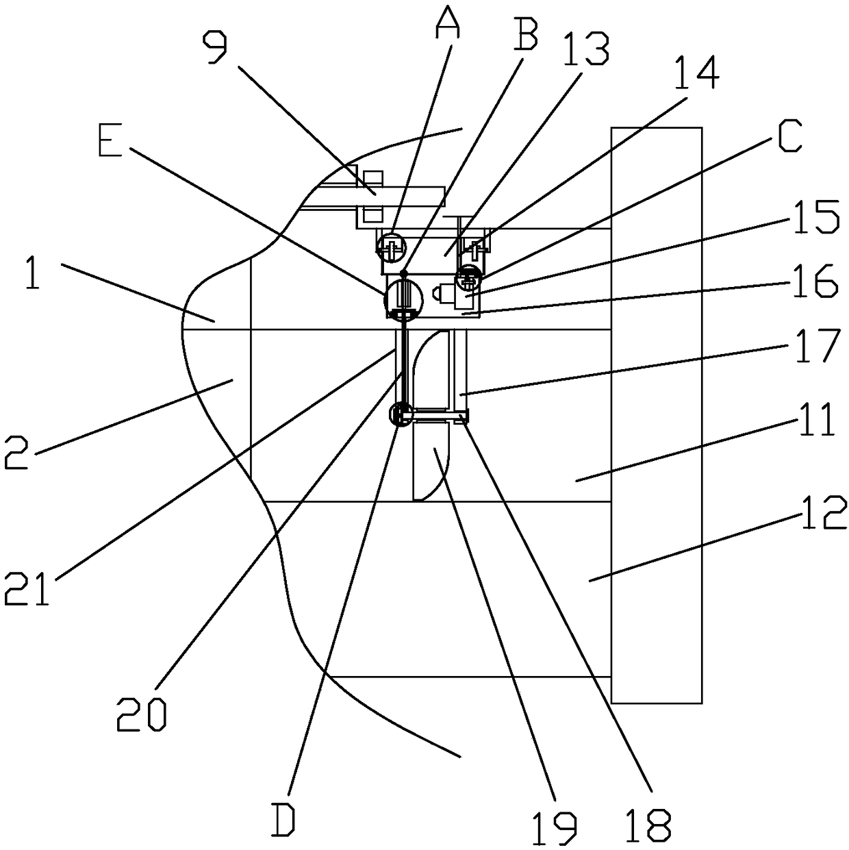
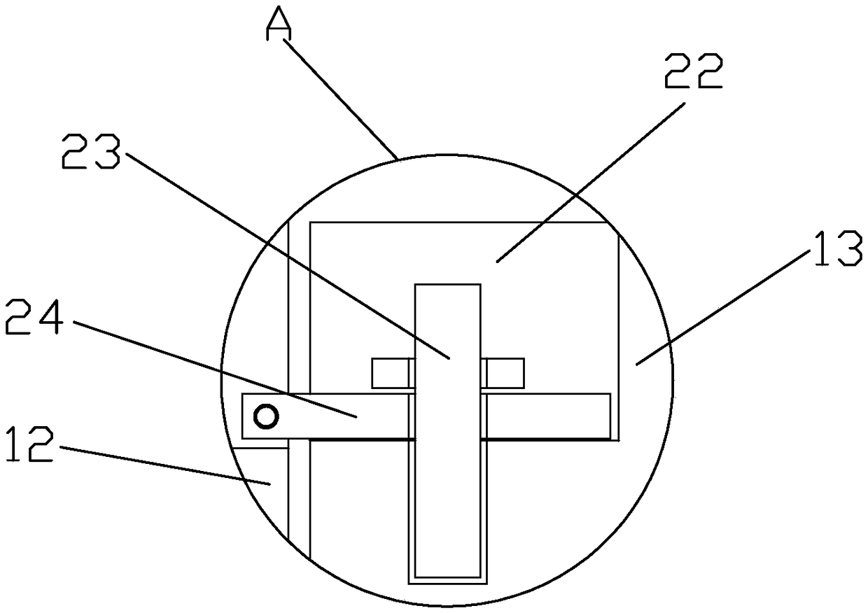
[0029] Such as Figure 1 to Figure 7 A gate valve that can automatically detect water flow velocity in real time is shown, including a valve body 1, a valve cover 4 and a connecting body 12, the valve cover 4 is installed above the valve body 1, and the connecting body 12 is installed on the right side of the valve body 1, The valve body 1 is provided with a circulation chamber 2, and the connecting body 12 is provided with a test chamber 11, the circulation chamber 2 communicates with the test chamber 11, and the internal thread of the data line 14 is inserted with a valve stem 6, and the valve stem 6 is threaded with a pressure The ring 5 and the pressure ring 5 are ins...


PUM


Abstract

The invention provides a sluice valve capable of automatically detecting water velocity in real time. The sluice valve comprises a valve body, a valve cover and a connecting body, wherein the valve cover is arranged above the valve body, and the connecting body is arranged on the right side of the valve body; a circulating cavity is formed in the valve body, a test cavity is formed in the connecting body, and the circulating cavity communicates with the test cavity; a valve rod is inserted into a data line in a threaded mode, a pressing ring is connected with the valve rod in a threaded and sleeving mode, and the pressing ring is installed in the valve cover; a handle is fixedly connected to the upper end of the valve rod, movable cavities are formed in the valve body and the valve cover,and a valve plate is rotatably connected to the lower end of the valve rod; the valve plate is clamped and connected to the inner portions of the movable cavities, the valve cover is fixedly connectedwith the valve body through a plurality of first threaded bolts in a threaded mode, and the connecting body is fixedly connected with the valve body through a plurality of second threaded bolts in athreaded mode; and a detection mechanism is installed in the test cavity, a connecting cavity is formed in the connecting body, and a transmission mechanism is installed in the connecting cavity.

Description

technical field [0001] The invention relates to the technical field of gate valves, in particular to a gate valve capable of automatically detecting water flow velocity in real time. Background technique [0002] The gate valve is an opening and closing gate, the movement direction of the gate is perpendicular to the direction of the fluid, the gate valve can only be fully opened and fully closed, and cannot be adjusted and throttled, the gate valve is sealed by the contact between the valve seat and the gate, usually sealed The surface will be surfacing with metal materials to increase wear resistance. [0003] The gate valve is a device that can cut off the water flow at any time. Generally, the gate valve is installed in the middle of the pipeline. The staff can control the gate valve at any time to decide whether the water flow needs to be cut off. The pipeline that needs to cut off the water flow generally has strict water control. However, because the gate valve is a ...

Claims


Application Information

Patent Timeline
Patent Type & Authority Applications(China)
IPC IPC(8): F16K27/08F16K27/04F16K37/00F16K3/30
CPCF16K3/30F16K27/041F16K27/08F16K37/005
Inventor 王宗钏
Owner 温州市斯罗登阀门配件有限公司
Why Eureka
Try Eureka