Gas stripping sludge discharge device

A sludge discharge device and air lift technology, which is applied in the feeding/discharging device of the sedimentation tank, sludge treatment, water/sludge/sewage treatment, etc. To achieve the effect of smooth air outlet, reduce equipment energy consumption, and prevent blockage

Inactive Publication Date: 2017-05-31
江苏鼎弘环境科技有限公司
View PDF9 Cites 0 Cited by
  • Summary
  • Abstract
  • Description
  • Claims
  • Application Information

AI Technical Summary

Problems solved by technology

[0003] However, the bell mouth is easy to block when sucking mud, resulting in poor mud suction, and the existing inlet pipe port is easy to enter the sludge, resulting in poor air outlet. After the sludge is sucked in

Method used


Image

  • Gas stripping sludge discharge device
  • Gas stripping sludge discharge device

Examples


Embodiment 1

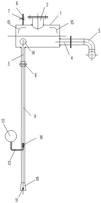
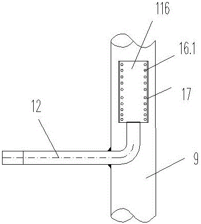
[0011] Embodiment 1: A kind of air lifting and sludge removal device, comprising a horizontal gas tank 1, a hand hole 2 is arranged on the side wall of the upper end of the gas tank 1, a mud inlet pipe 3 is arranged on the side wall near the left end of the lower end of the gas tank 1, and the gas tank 1 There is a mud outlet pipe 4 near the bottom of the right end, the mud outlet pipe 4 is connected to the sludge main pipe 5 through a flange, an exhaust pipe 6 is arranged on the side of the hand hole 2, a gate valve 7 is arranged on the exhaust pipe 6, and the mud inlet pipe 3 passes through The joint 8 is connected to the suction pipe 9, the bottom of the suction pipe 9 is provided with a suction bell mouth 10, and the center of the suction bell mouth 10 is provided with a rice-shaped rotating paddle 11, and the suction pipe 9 is located at 1 / 3 from bottom to top. An air intake pipe 12 is arranged at the height, and the air intake pipe 12 is connected to the blower 13. The ai...


PUM


Abstract

The invention provides a gas stripping sludge discharge device comprising a horizontal gas tank, wherein a hand hole is formed in a side wall of an upper end of the gas tank, a sludge inlet pipe is arranged at a position close to the side wall of a left end on a lower end of the gas tank, a sludge outlet pipe is arranged at a position close to the bottom on a right end of the gas tank, the sludge outlet pipe is connected with a sludge header pipe, an exhaust pipe is arranged on one side of the hand hole, a brake valve is arranged on the exhaust pipe, the sludge inlet pipe is connected with a sludge suction pipe through a movable joint, a sludge suction horn mouth is arranged at a bottom end of the sludge suction pipe, a *-shaped rotating blade is arranged at the center of the sludge suction horn mouth, an air inlet pipe is arranged at a 1/3 height of the sludge suction pipe from bottom to top, the air inlet pipe is connected with a blower, the air inlet pipe stretches into the sludge suction pipe, the pipe orifice is vertically upward, a flow guide ball is arranged right above the sludge suction pipe in the gas tank, and symmetrical arc-shaped flow guide plates are arranged on the top left side and the top right side of the gas tank.

Description

technical field [0001] The invention relates to the field of sludge treatment, in particular to a sludge gas lift device. Background technique [0002] The air-lift mud discharge device consists of an air-lift tank, a mud outlet pipe, a mud inlet pipe, an exhaust pipe, an air inlet pipe, a mud suction bell, and a mud suction bell bracket. The mud suction bell bracket is set on the One end of the mud suction bell is fixed on the bottom of the sludge tank, and the other end of the mud suction bell is connected to the mud inlet pipe; when working, inject compressed air into the inlet pipe, and the compressed air drives the air in the mud inlet pipe to flow to the gas tank. After the mud is pumped into the mud inlet pipe, it flows to the gas tank. [0003] However, the bell mouth is easy to block when sucking mud, resulting in poor mud suction, and the existing inlet pipe port is easy to enter the sludge, resulting in poor air outlet. After the sludge is sucked into the tank, t...

Claims


Application Information

Patent Timeline
IPC IPC(8): B01D21/24C02F11/00
CPCB01D21/2466C02F11/00
Inventor 徐忠杨姜殿鹏鲁超
Owner 江苏鼎弘环境科技有限公司
Why Eureka
Try Eureka