Automatic punching device

A stamping equipment and automatic technology, applied in metal processing equipment, feeding devices, manufacturing tools, etc., can solve the problems of low processing efficiency of automatic stamping equipment, improve the feeding speed, prevent deviation or deformation, and improve processing efficiency. Effect

Active Publication Date: 2017-05-31
江苏环海机械科技有限公司
View PDF7 Cites 4 Cited by
  • Summary
  • Abstract
  • Description
  • Claims
  • Application Information

AI Technical Summary

Problems solved by technology

However, when there are multiple parts to be punched on the workpiece, in order to avoid deformation of the workpiece, generally only one workpiece is stamped at a time, resulting in low processing efficiency of the automatic punching equipment

Method used


Image

  • Automatic punching device
  • Automatic punching device
  • Automatic punching device

Examples


Embodiment Construction

[0020] In order to make the above objects, features and advantages of the present invention more comprehensible, specific implementations of the present invention will be described in detail below in conjunction with the accompanying drawings. In the following description, numerous specific details are set forth in order to provide a thorough understanding of the present invention. However, the present invention can be implemented in many other ways different from those described here, and those skilled in the art can make similar improvements without departing from the connotation of the present invention, so the present invention is not limited by the specific implementations disclosed below.

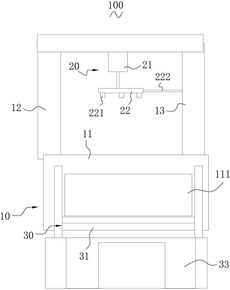
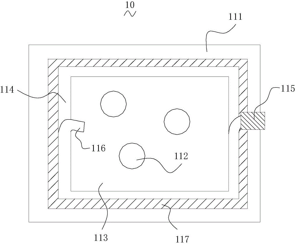
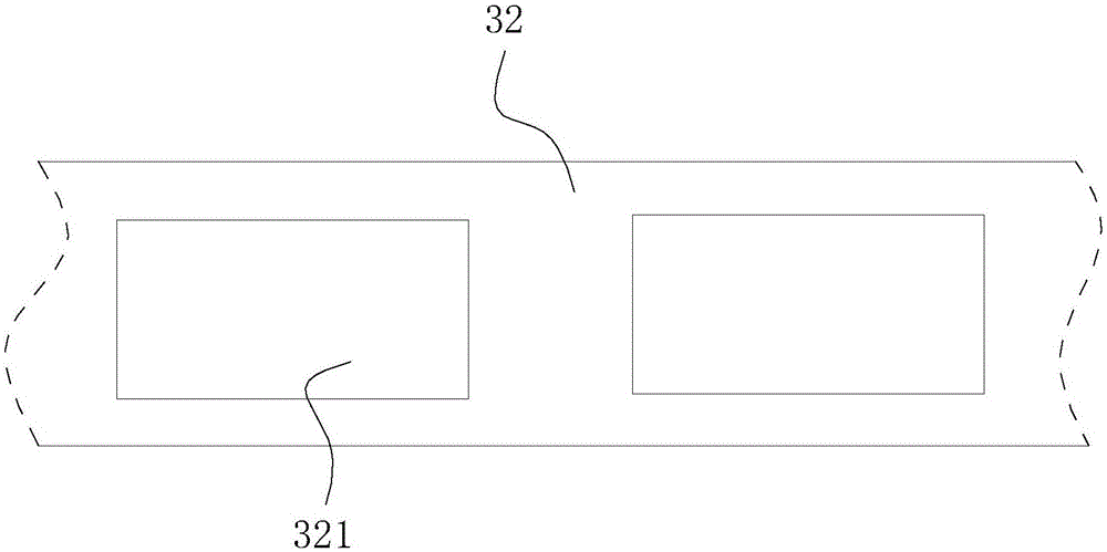
[0021] The present invention relates to an automatic punching equipment. The automatic punching equipment includes a base, a punching assembly, and a feeding assembly. A punching platform is formed on the base and a supporting portion protrudes adjacent to the punching platform. A fee...


PUM

PropertyMeasurementUnit
Thicknessaaaaaaaaaa

Abstract

The invention relates to an automatic punching device. The automatic punching device comprises a base, a punching assembly and a feeding assembly; a punching platform is arranged on the base; a supporting part is arranged on the base in a protruding mode; a feeding channel is arranged in the punching platform; a plurality of punching holes are formed in the surface of the punching platform; the punching assembly comprises a driving part and a punch; the feeding assembly comprises a pulling piece and a feeding belt; a plurality of containing cavities are formed in the feeding belt; a guide rod is further arranged on the base in a protruding mode, and the guide rod and the supporting part are arranged at intervals; a guide sliding groove is arranged on the guide rod in a concave mode; a plurality of punching ends are arranged on the punch; and a guide bar is further arranged on the side wall of the punch in a protruding mode and is arranged in the guide sliding groove in a sliding mode. The automatic punching device is high in machining efficiency.

Description

technical field [0001] The invention relates to an automatic punching equipment. Background technique [0002] In industrial production, punching equipment is often required to punch workpieces. However, the step of punching a workpiece generally includes positioning the workpiece and a drive member moving the punch toward said workpiece. However, when there are multiple parts to be punched on the workpiece, in order to avoid deformation of the workpiece, generally only one workpiece is punched at a time, resulting in low processing efficiency of the automatic punching equipment. Contents of the invention [0003] Based on this, it is necessary to provide an automatic stamping device with high processing efficiency. [0004] An automatic stamping equipment, including a base, a stamping assembly, and a feeding assembly, a stamping platform is formed on the base and a supporting portion protrudes adjacent to the stamping platform, and a laterally extending feeding channel ...

Claims


Application Information

Patent Timeline
IPC IPC(8): B21D28/24B21D43/12B21D37/01
CPCB21D28/24B21D37/01B21D43/12
Inventor 尹茜
Owner 江苏环海机械科技有限公司
Why Eureka
Try Eureka