
Material pulling structure of continuous progressive die

A technology of progressive die and drawing needle, applied in the field of stamping, can solve the problems of insufficient strength, affecting the efficiency and quality of stamping, and sending the material to the die.

Active Publication Date: 2017-05-31
金德精密配件(苏州)有限公司
View PDF6 Cites 0 Cited by
  • Summary
  • Abstract
  • Description
  • Claims
  • Application Information

AI Technical Summary

Problems solved by technology

However, when the strip is particularly thin, its strength is insufficient, and there is a certain distance between the feeder and the mold, the strip between the feeder and the mold will sag and deform, and the feeder cannot smoothly send the strip to the mold, let alone Make the material belt move forward according to a fixed step distance, which seriously affects the stamping efficiency and quality

Method used


Image

  • Material pulling structure of continuous progressive die
  • Material pulling structure of continuous progressive die
  • Material pulling structure of continuous progressive die

Examples


Embodiment

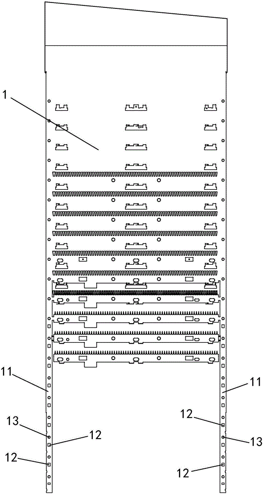
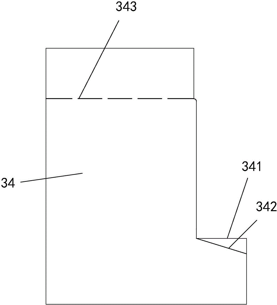
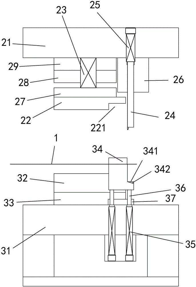
[0039] see Figure 1~Figure 9 As shown, a kind of drawing structure of continuous progressive die comprises material belt 1, lower mold and upper mold, and lower mold comprises lower mold base 31 and lower template 32, and lower template 32 is arranged on the top of lower mold base 31, and lower template 32 and the lower die base 31 are provided with a lower backing plate 33, and the upper die includes an upper die base, 2 and an upper stripping plate 22, and the upper stripping plate 22 is located below the upper die base 21, and the upper die base 21 and the upper stripping plate 22 An upper backing plate 29, an upper splint 28 and a back-off plate 27 are arranged sequentially from top to bottom.

[0040] The guide edges 11 on both sides of the material belt 1 are provided with drawing holes 12, and the drawing holes 12 are distributed at intervals in the length direction of the material belt 1, and the distance between adjacent drawing holes 12 is the same as that of the co...


PUM


Abstract

A material pulling structure of a continuous progressive die comprises a material belt, a lower die body and an upper die body, and is characterized in that guide edges on the two sides of the material belt are provided with material pulling holes; a lower die base is provided with a buoyancy lift block; a conveying channel is formed in the part, corresponding to the material belt, of the buoyancy lift block; the buoyancy lift block is provided with a limiting step, and the limiting steps corresponds to a material pulling pin; the vertical distance between the upper surface of the limiting step and the conveying channel is matched with the step pitch of the continuous progressive die; an upper disengagement plate is connected with an upper die base through a third spring; the upper die base is provided with the material pulling pin, and the material pulling pin is connected with the upper die base through a second spring and located in front of a lower die plate; an avoiding groove is formed in the part, corresponding to the upper portion of the buoyancy lift block, of the upper disengagement plate; in the conveying direction of the material belt, the buoyancy lift block is located between the lower die plate and the material pulling pin; and the elastic force of the third spring is larger than that of first springs, and the elastic force of the first springs is larger than that of the second spring.

Description

technical field [0001] The invention relates to the stamping field, in particular to a drawing structure of a continuous progressive die. Background technique [0002] The continuous progressive die is composed of multiple stations, and each station is connected in sequence to complete different processes, and a series of different stamping processes are completed in one stroke of the punching machine. After a stroke is completed, the punch feeder moves the material belt forward according to a fixed step, so that multiple processes can be completed on a pair of molds. However, when the strip is particularly thin, its strength is insufficient, and there is a certain distance between the feeder and the mold, the strip between the feeder and the mold will sag and deform, and the feeder cannot smoothly send the strip to the mold, let alone The material belt is moved forward according to a fixed step distance, which seriously affects the stamping efficiency and quality. Conten...

Claims


Application Information

Patent Timeline
Patent Type & Authority Applications(China)
IPC IPC(8): B21D43/06B21D37/08
CPCB21D37/08B21D43/06
Inventor 贺林武英战刘新泉陈海平石乾雷
Owner 金德精密配件(苏州)有限公司
Learn More