Multifunctional hydraulic spanner

A hydraulic wrench, multi-functional technology, applied in the wrench field, can solve the problem of single function of the wrench, and achieve the effect of reducing procurement costs

Inactive Publication Date: 2017-05-31
海恩拓克工业装备(武汉)有限公司
View PDF13 Cites 5 Cited by
  • Summary
  • Abstract
  • Description
  • Claims
  • Application Information

AI Technical Summary

Problems solved by technology

[0004] The present invention mainly solves the technical problem of the single function of the wrench existing in the prior art, and proposes a multifunctional hydraulic wrench,

Method used


Image

  • Multifunctional hydraulic spanner
  • Multifunctional hydraulic spanner
  • Multifunctional hydraulic spanner

Examples


Example Embodiment

[0025] Example:

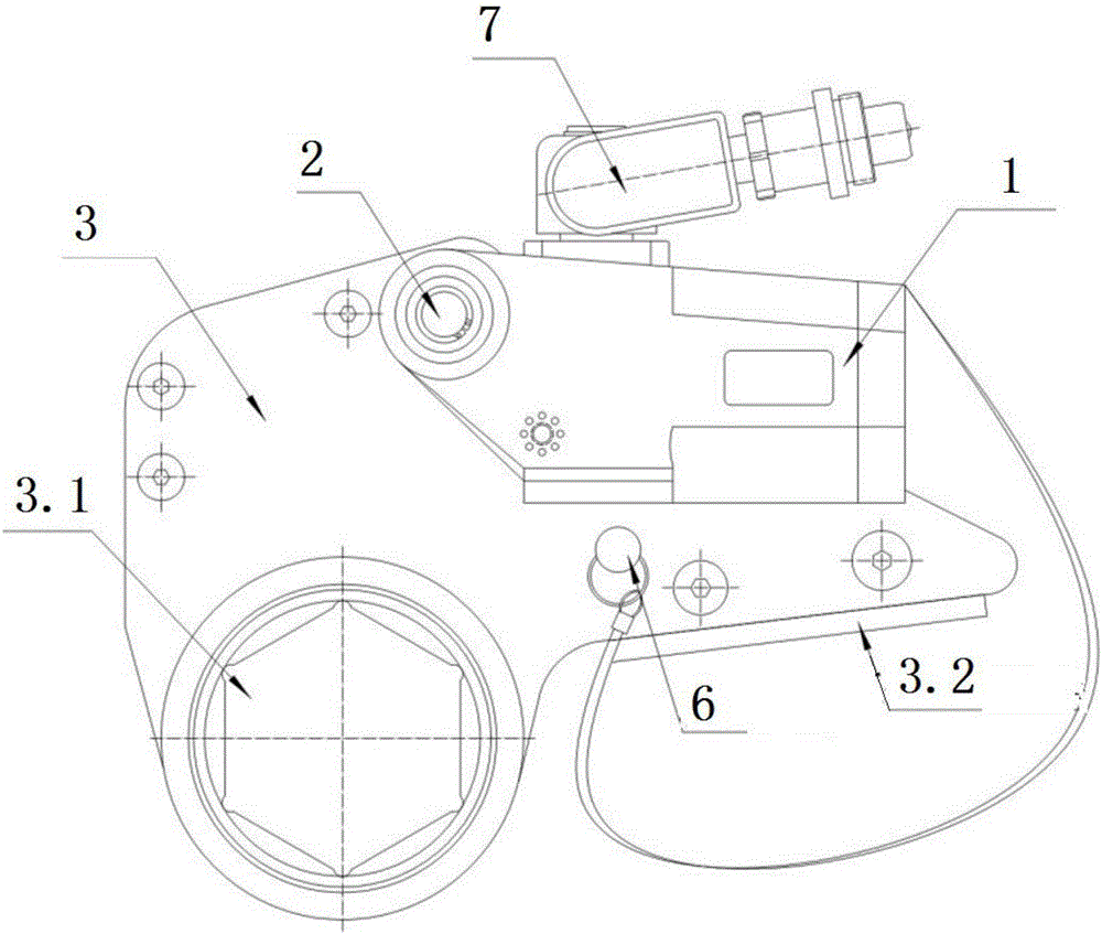
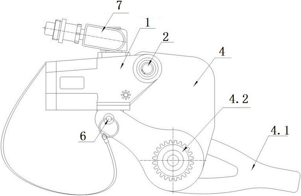
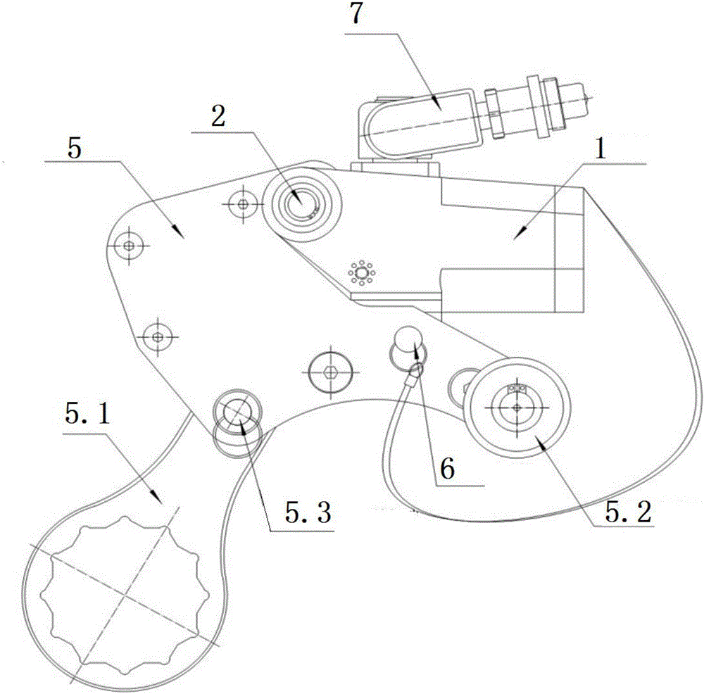
[0026] A multifunctional hydraulic wrench, comprising: a working head assembly, a power head assembly 1, the working head assembly includes several different working heads, the power head assembly 1 is hingedly arranged on the working head assembly through the power head assembly fixing rod 2, and its output end It is connected with the power adapting device on the working head assembly; the power head assembly 1 is provided with a safety rope, and one end of the safety rope is fixed on the working head through the safety bolt 6 of the power head assembly.

[0027] The working head assembly includes one or more of the hollow working head 3, the square drive working head 4, and the opening working head 5;

[0028] figure 1 It is a schematic diagram of the connection between the power head assembly 1 and the hollow working head 3 in this embodiment.

[0029] The hollow working head 3 is provided with a hollow driving head 3.1 for installing different sleeves,...


PUM


Abstract

The invention relates to a spanner, in particular to a multifunctional hydraulic spanner. The multifunctional hydraulic spanner comprises a work head assembly and a power head assembly. The work head assembly comprises a plurality of different work heads. The power head assembly is hinged to the work head assembly through power head assembly fixing rods, and the output end of the power head assembly is connected with a power adaptive device on the work head assembly. According to the spanner, the various work heads can be flexibly selected and matched to be used, rapid changing is achieved to meet various working conditions, and all bolt challenges are solved.

Description

technical field [0001] The invention relates to a wrench, in particular to a multifunctional hydraulic wrench. Background technique [0002] The hydraulic wrench in the prior art has a single function. The power head and the working head adopt an integrated structure. One power head can only be matched with one working head. When the bolts are different, different types of hydraulic wrenches need to be selected. Users need to purchase multiple sets of hydraulic wrenches, which increases the purchase cost. [0003] In view of this, on the basis of many years of relevant work experience, the inventor has proposed a multifunctional hydraulic wrench through painstaking research. The wrench can be flexibly selected and used with a variety of working heads, which can be quickly transformed to meet various working conditions and solve all bolting challenges. Contents of the invention [0004] The present invention mainly solves the technical problem of the single function of th...

Claims


Application Information

Patent Timeline
IPC IPC(8): B25B21/00
CPCB25B21/00
Inventor 顾斌
Owner 海恩拓克工业装备(武汉)有限公司
Why Eureka
Try Eureka