Mechanical paw

A technology of manipulator claw and drive mechanism, applied in manipulators, program-controlled manipulators, chucks, etc., can solve problems such as affecting the precision of thin-plate and disc-shaped workpieces, unable to realize 180° turning of thin-plate and disc-shaped workpieces, etc., and achieves movement guidance and reset. smooth effect

Active Publication Date: 2017-05-31
高维智控机器人科技(苏州)有限公司
View PDF10 Cites 7 Cited by
  • Summary
  • Abstract
  • Description
  • Claims
  • Application Information

AI Technical Summary

Problems solved by technology

[0004] With the development of science and technology, in order to improve the quality and production efficiency of workpieces, manipulators are gradually used in industrial production to replace manual operations. At present, when automatic loading and unloading of some thin disc-shaped workpieces, suction cups are usually used The top of the thin plate disc-shaped workpiece or the method of grabbing from the top with the three-jaw mechanical claw is used for loading and unloading work, but this method can only realize the parallel movement of the thin plate disc-shaped workpiece, and cannot be used during the loading and unloading process. Realize the action of flipping the thin plate disc-shaped workpiece by 180°, and when the precision of the upper and lower surfaces of the thin plate disc-shaped workpiece is high, using a suction cup to suck on the thin plate disc-shaped workpiece will affect the accuracy of the thin plate disc-shaped workpiece

Method used


Image

  • Mechanical paw
  • Mechanical paw
  • Mechanical paw

Examples


Embodiment Construction

[0019] The mechanical gripper of the present invention will be further described below in conjunction with the accompanying drawings and specific embodiments:

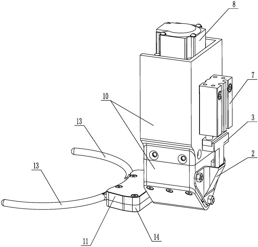
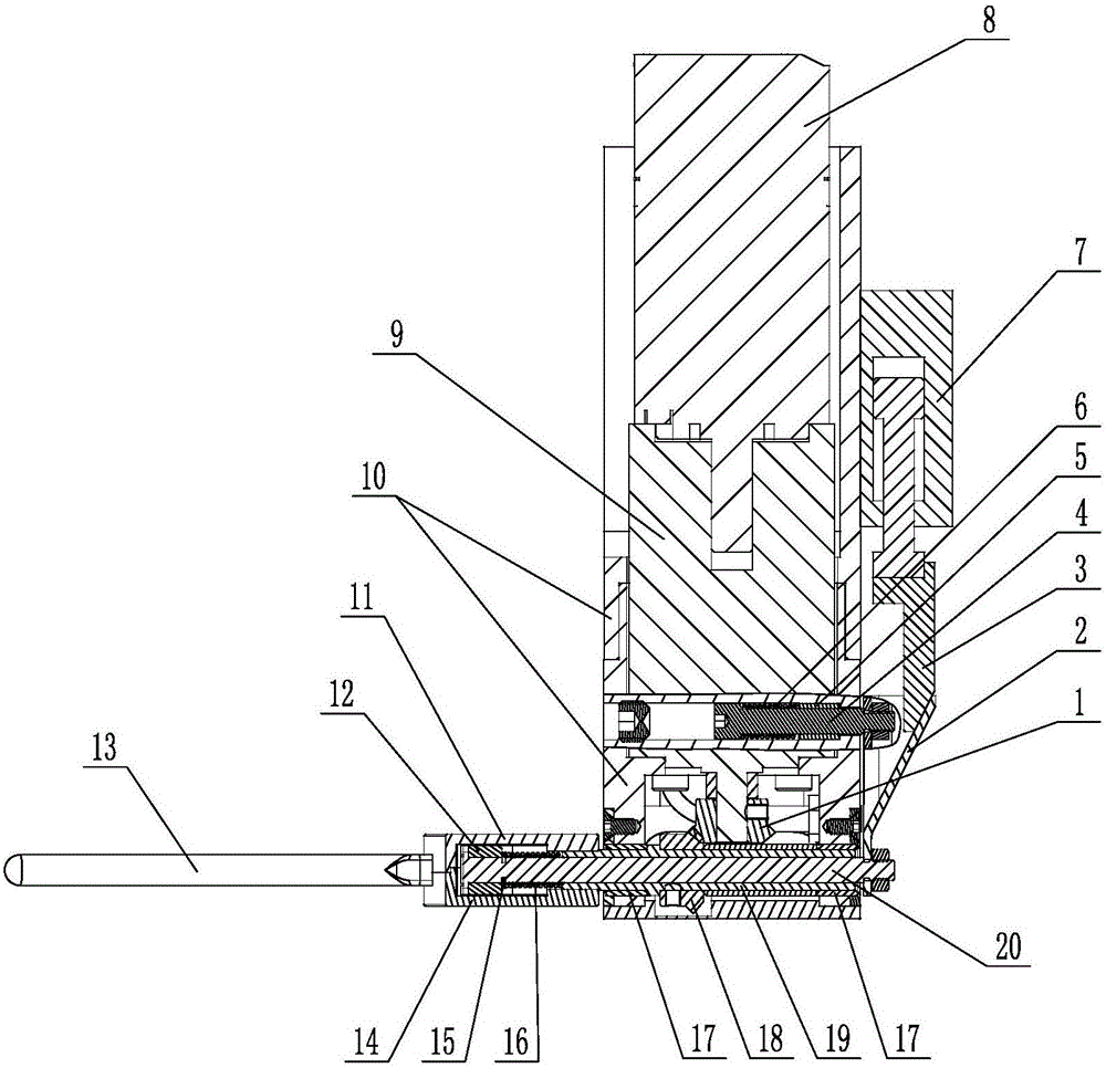
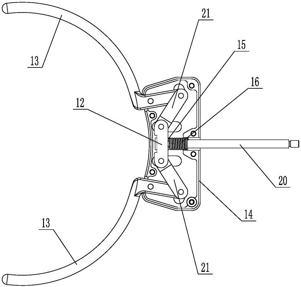
[0020] Such as Figure 1 to Figure 4 As shown, the manipulator claw of the present invention includes a bracket 10, a hollow rotating shaft 19, an upper cover plate 11 and a lower cover plate 14, the hollow rotating shaft 19 is rotatably connected with the support 10 through two first oil-free bushings 17, and the upper cover plate 11 and the The lower cover plate 14 is fastened and connected together, the upper cover plate 11 and the lower cover plate 14 are connected together with the end of the hollow rotating shaft 19, and there are two hinged joints between the upper cover plate 11 and the lower cover plate 14 for being clamped on the thin plate circle. The arc-shaped clamping fingers 13 on the side of the disc-shaped workpiece 101, the cross-section of the arc-shaped clamping fingers 13 is circular and the diamet...


PUM


Abstract

The invention discloses a mechanical paw, and belongs to an end effector of a mechanical arm. The mechanical paw comprises a support, a hollow rotating shaft, an upper cover plate and a lower cover plate. The hollow rotating shaft is connected with the support in a rotatable mode through a first oil-free bush. The upper cover plate and the lower cover plate are buckled and connected together and are together connected with the end of the hollow rotating shaft. Two arc-shaped clamping fingers used for clamping the side face of a thin plate disc-shaped workpiece are hinged between the upper cover plate and the lower cover plate. The cross section of each arc-shaped clamping finger is circular, and the diameter of each arc-shaped clamping finger is smaller than the thickness of the thin plate disc-shaped workpiece. The two arc-shaped clamping fingers are connected with a first driving mechanism used for opening and closing the arc-shaped clamping fingers. The support is provided with a second driving mechanism used for driving the hollow rotating shaft to rotate. By means of the mechanical paw, in the feeding and discharging processes of the thin plate disc-shaped workpiece, precision of the upper surface and the lower surface of the thin plate disc-shaped workpiece cannot be affected, and meanwhile overturning movement can be completed.

Description

[0001] Technical field: [0002] The invention relates to an end effector of a manipulator, specifically a manipulator claw. [0003] Background technique: [0004] With the development of science and technology, in order to improve the quality and production efficiency of workpieces, manipulators are gradually used in industrial production to replace manual operations. At present, when automatic loading and unloading of some thin disc-shaped workpieces, suction cups are usually used The top of the thin plate disc-shaped workpiece or the method of grabbing from the top with the three-jaw mechanical claw is used for loading and unloading work, but this method can only realize the parallel movement of the thin plate disc-shaped workpiece, and cannot be used during the loading and unloading process. Realize the action of flipping the thin disc-shaped workpiece by 180°, and when the precision of the upper and lower surfaces of the thin-plate disc-shaped workpiece is high, using a s...

Claims


Application Information

Patent Timeline
Patent Type & Authority Applications(China)
IPC IPC(8): B25J9/04B25J15/02
CPCB25J9/04B25J15/0213Y02P70/10
Inventor 袁建军蔡玉鹏
Owner 高维智控机器人科技(苏州)有限公司
Why Eureka
Try Eureka