De-molding and resetting device for injection molding of herringbone gear

A technology of injection molding and herringbone gear, applied in the field of injection molding demoulding and reset device, can solve the problems of easy wear, poor molding quality, large core resistance, etc.

Active Publication Date: 2017-05-31
CHANGZHOU INST OF TECH
View PDF2 Cites 8 Cited by
  • Summary
  • Abstract
  • Description
  • Claims
  • Application Information

AI Technical Summary

Problems solved by technology

Aiming at the problem of demoulding after injection molding of herringbone gears (equivalent to bidirectional plastic helical gears with equal diameters), in current practice, mandrels are set in the movable and fixed molds respectively to form helical tooth grooves (the number of core rods is equal to the number of helical tooth grooves). Quantity), after the mold is opened, the connecting rod device drives the forming core rod of the helical groove to pull out obliquely, so as to realize the two-way core pulling of the movable and fixed mold, but the mold structure is complex, the parts processing is cumbersome, the assembly accuracy is low, and the molding quality is poor
There is also a structure that uses two helical gear cavities to be embedded in combination, the fixed mold plate to be rotated and pushed out, the arc-shaped bent pin to be reset, and the movable mold core to be rotated and pushed out in two stages, but this structure has at least the following deficiencies: 1. The upper arc of the fixed mold cavity It is difficult to process the guide hole of the bent pin; 2. It is difficult to control the consistency between the radian of the arc-shaped bent pin and the rotation angle of the fixed mold cavity; 3. The resistance of the core rotation is large and easy to wear; 4. It is not easy to ensure the angle of the core rotation and The speed is consistent with the helix angle of the helical gear; 5. The movement of the secondary push-out mechanism is not flexible

Method used


Image

  • De-molding and resetting device for injection molding of herringbone gear
  • De-molding and resetting device for injection molding of herringbone gear
  • De-molding and resetting device for injection molding of herringbone gear

Examples


Embodiment Construction

[0038] In order to facilitate the understanding of those skilled in the art, the present invention will be further described below in conjunction with the embodiments and accompanying drawings.

[0039] This embodiment is used for injection molding mould, and mold is installed on the horizontal injection machine.

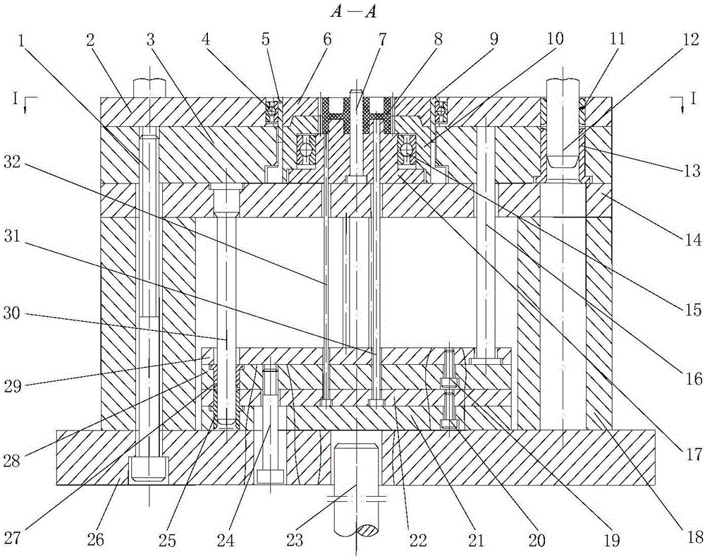
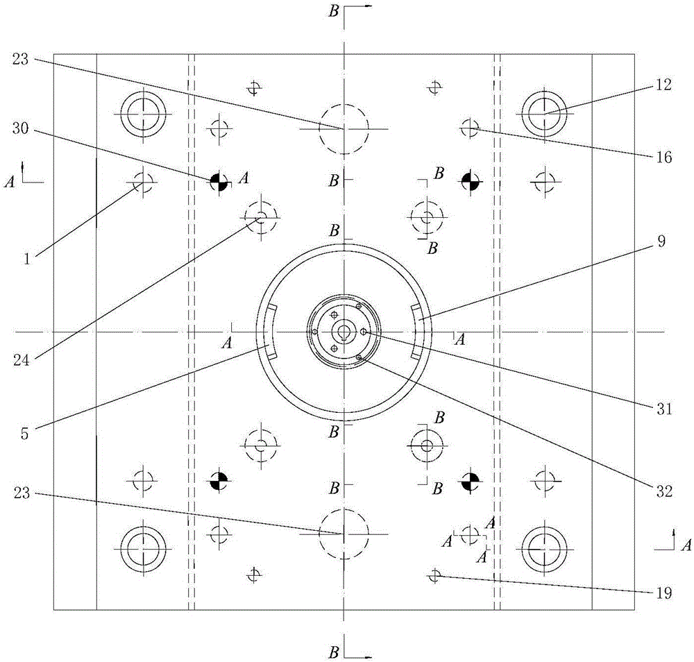
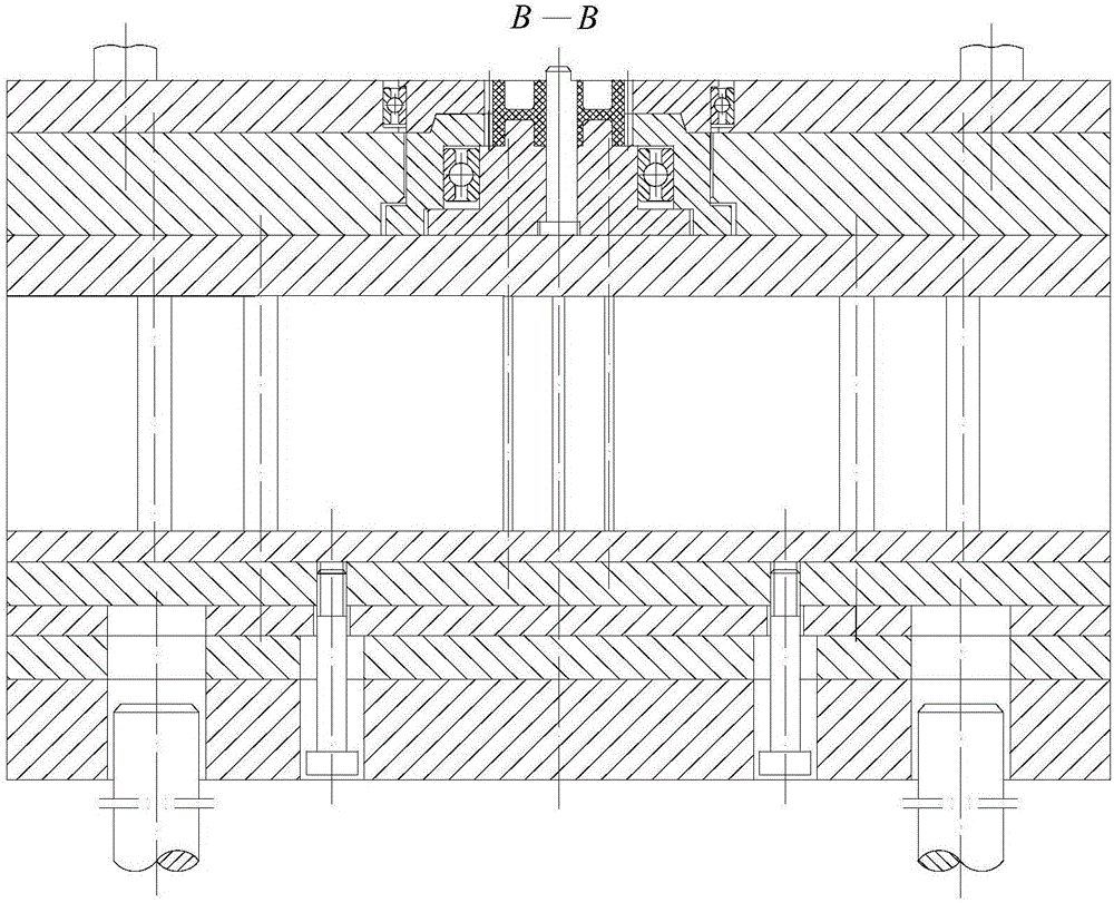
[0040] After the injection molding is completed, under the action of the mold opening mechanism of the injection machine, the movable mold part moves along the figure 1 The shown parting surface I-I retreats to the set position. figure 2 It mainly reflects the distribution positions of guide pillars, hexagon socket screws, helical gear cavities, positioning inserts, push rods, push plate guide pillars, connecting rods, ejector rods of injection machines and other parts. figure 1 is the A-A sectional view of the device, image 3 It is a B-B cross-sectional view of the device.

[0041] The device includes from top to bottom: cavity fixing plate 2, movable template...


PUM


Abstract

The invention discloses a de-molding and resetting device for injection molding of a herringbone gear. The de-molding and resetting device sequentially comprises a cavity fixing plate, a movable mold plate, a bearing plate, cushion blocks and a movable mold base plate from up to down; a front-section centripetal thrust bearing is arranged in a mounting hole of the cavity fixing plate; a front-section helical gear cavity is formed in the inner side of the front-section centripetal thrust bearing; the movable mold plate internally comprises a rear-section helical gear cavity; positioning inserts are arranged on the side surface of the front-section helical gear cavity and are matched with positioning grooves formed in the corresponding position of the outer side of the rear-section helical gear cavity; a movable mold core insert is arranged in the rear-section helical gear cavity; a rear-section centripetal thrust bearing is arranged between the rear-section helical gear cavity and the movable mold core insert; a mold core with a forming center hole is arranged in the movable mold core insert; and a two-stage sequential pushing mechanism is arranged on a movable mold base plate and between the cushion blocks on the two sides of the movable mold base plate. According to the de-molding and resetting device, the two-section helical gear cavities rotate sequentially so that the herringbone gear can be smoothly de-molded, and two helical tooth grooves opposite in the rotating direction are enabled to be aligned to the forming position in the mold-closing and resetting processes by means of the positioning inserts.

Description

technical field [0001] The ejection and reset device for injection molding of herringbone gears of the present invention is suitable for the design and application of the mechanism design and application of the herringbone plastic gears being separated from the mold cavity after injection molding and the cavity being aligned and reset when the mold is closed. Background technique [0002] There are three types of gear transmission with parallel shafts: spur gears, helical gears, and herringbone gears. The herringbone gear is equivalent to the combination of two helical gears. The structure is symmetrical, the diameter is equal, and the direction of rotation of the tooth profile is opposite. With the advantages of high height, small axial load, high bearing capacity, and stable operation, herringbone gear transmission is an important development direction of gear transmission mechanisms. After the herringbone plastic gear is injection molded, to make the two segments of the ...

Claims


Application Information

Patent Timeline
Patent Type & Authority Applications(China)
IPC IPC(8): B29C45/40B29C45/66
CPCB29C45/4005B29C45/66B29C2045/4042B29C2045/648
Inventor 江昌勇江妦李丹虹黄志荣沈洪雷
Owner CHANGZHOU INST OF TECH
Why Eureka
Try Eureka