Rotary charging pile with anti-collision function

A technology of rotating and charging piles, applied in charging stations, electric vehicle charging technology, electric vehicles, etc., can solve the problems of inability to rotate and adjust, the interface position is off-line, and good work performance, so as to achieve precise rotation and adjustment of charging angle, reduce Maintenance cost, good effect of anti-collision performance

Inactive Publication Date: 2017-05-31
林燕兰 +1
View PDF5 Cites 14 Cited by
  • Summary
  • Abstract
  • Description
  • Claims
  • Application Information

AI Technical Summary

Problems solved by technology

[0004] In order to solve the above problems, the present invention provides a rotating charging pile with anti-collision performance, which can solve the problem of large bending and folding of the charging gun connection line caused by the inability of the existing charging pile to rotate and adjust the charging angle at the charging gun interface. The interface position between the charging gun connection line and the charging pile is off-line or broken, and the existing charging pile is difficult to open due to the overcrowded charging of electric vehicles. It is often damaged by collisions, and the charging pile can be precisely rotated and adjusted to charge at the charging gun interface. Angle and stable anti-collision functions greatly reduce the maintenance cost of the charging pile, and the work performance is good

Method used


Image

  • Rotary charging pile with anti-collision function
  • Rotary charging pile with anti-collision function
  • Rotary charging pile with anti-collision function

Examples


Embodiment Construction

[0024] In order to make the technical means, creative features, goals and effects achieved by the present invention easy to understand, the present invention will be further described below in conjunction with specific illustrations.

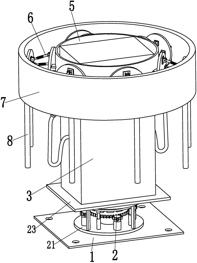
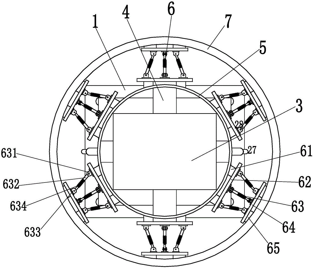
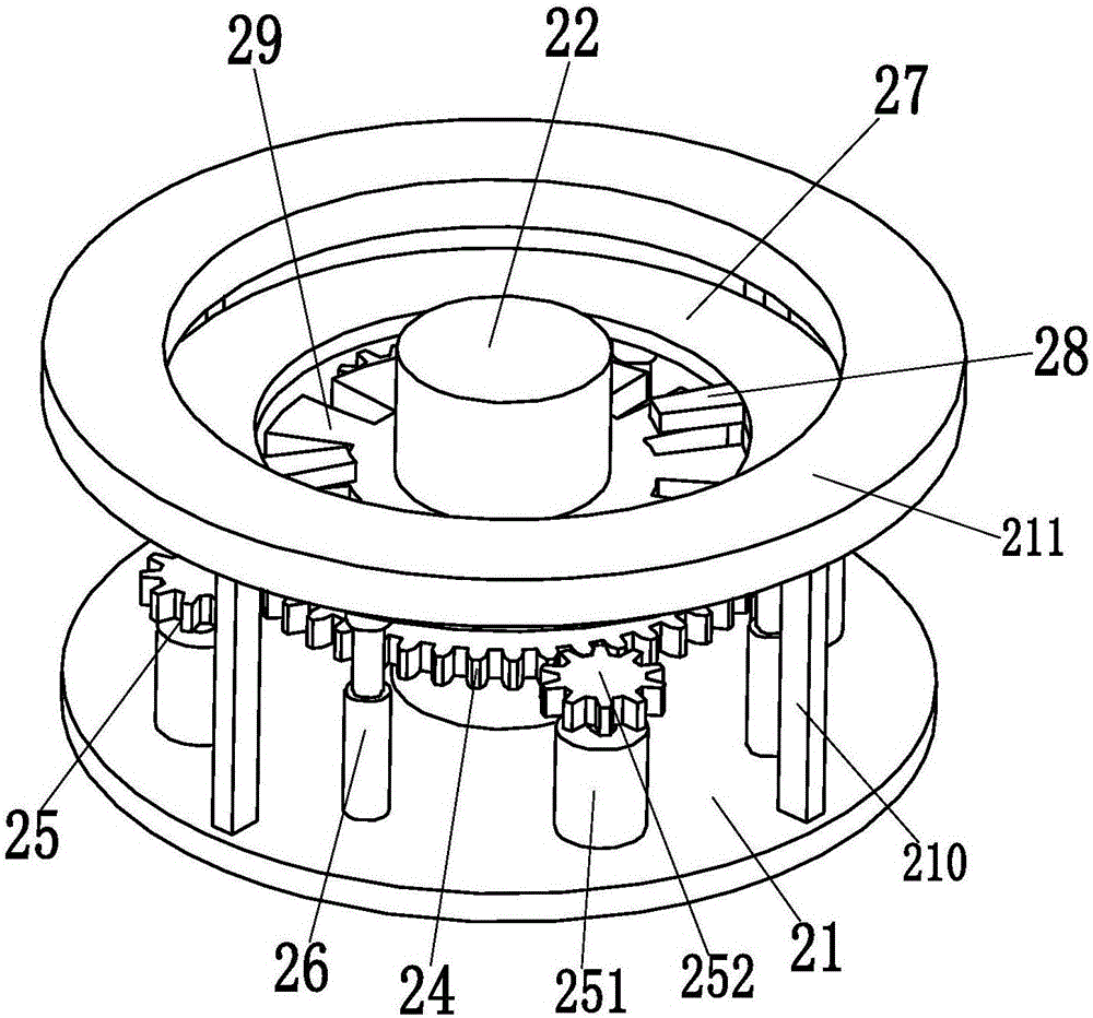
[0025] Such as Figure 1 to Figure 5 As shown, a rotary charging pile with anti-collision performance includes a bottom plate 1, four mounting holes are symmetrically installed on the bottom plate 1, and the present invention is installed on the operation ground through the four mounting holes, and the operation is simple and convenient. The upper end surface of 1 is equipped with a rotating mechanism 2, and the upper end surface of the rotating mechanism 2 is installed with a pile body 3, and two charging guns are symmetrically linked on the pile body 3, and the rotating mechanism 2 can accurately adjust the rotation angle of the pile body 3, so that it can be accurately Adjust the charging angle of the charging gun interface on the pile body 3...


PUM


Abstract

The invention relates to a rotary charging pile with an anti-collision function. The rotary charging pile comprises a bottom plate, wherein a rotating mechanism is mounted on the upper end face of the bottom plate; a pile body is mounted on the upper end face of the rotating mechanism; four rib posts are respectively welded on four side faces of the upper end of the pile body; annular supporting rings are welded on outer walls of the four rib posts; a circle of damping supporting mechanisms are uniformly mounted on the outer walls of the annular supporting rings along a central axis; the top ends of all the damping supporting mechanisms are welded on damping supporting rings; the damping supporting mechanisms can provide good damping performance and rigid supporting performance for the damping supporting rings; anti-collision posts are uniformly arranged on the lower end faces of the damping supporting rings along the central axis; and due to the uniformly distributed anti-collision posts, the phenomenon that the surface of the pile body is collided by an electric automobile can be avoided. According to the rotary charging pile disclosed by the invention, the functions of accurately rotating the charging pile to adjust a charging angle at a joint of a charging gun and realizing stable collision prevention can be realized, the maintenance cost of the charging pile is greatly reduced, and the operating performance is excellent.

Description

technical field [0001] The invention relates to the technical field of charging piles, in particular to a rotating charging pile with anti-collision performance. Background technique [0002] The charging pile can charge various types of electric vehicles according to different voltage levels. The charging pile can realize charging by timing, electricity meter, and amount, and can be used as a power purchase terminal for citizens. At present, it is mainly fixed on the ground or walls, and installed in public buildings, shopping malls, public parking lots, office buildings, government buildings and other public buildings or parking lots in residential quarters. The input end of the charging pile is directly connected to the AC grid, and the output end is equipped with a charging plug for charging the electric vehicle. [0003] With the increasing number of existing electric vehicles, the demand for charging piles and parking charging positions is relatively large. Usually, a...

Claims


Application Information

Patent Timeline
IPC IPC(8): B60L11/18
CPCB60L53/16B60L53/31Y02T10/70Y02T10/7072Y02T90/12Y02T90/14
Inventor 冒鹏飞
Owner 林燕兰
Why Eureka
Try Eureka