Motor vehicle with electric drive

a technology of electric drive and motor vehicle, which is applied in the direction of electric vehicles, electric devices, battery/cell propulsion, etc., can solve the problems of affecting the safety of electric vehicles, and requiring a relatively long charging time for storage modules, etc., to achieve simple and quick exchange of storage modules and good crash resistance

Inactive Publication Date: 2013-09-17
BENTELER AUTOMOBILTECHNIK GMBH
View PDF18 Cites 5 Cited by
  • Summary
  • Abstract
  • Description
  • Claims
  • Application Information

AI Technical Summary

Benefits of technology

[0004]One object of the present invention is to provide a motor vehicle having an electric drive in which exchanging storage modules is simple and quick, and in which the storage modules can also be secured or attached with good crash resistance.
[0007]In the present inventive motor vehicle, the storage module or modules are supported and / or arranged in a guide that extends longitudinally along the motor vehicle. The storage modules are longitudinally displaceable relative to the guide. This construction simplifies the loading of the storage modules into the motor vehicle. Naturally, it also simplifies removing the storage modules from the motor vehicle. In addition, an impact damping unit may also be arranged at one or both ends of the guide. The present invention takes into consideration that the storage modules are relatively heavy, and consequently may move within the longitudinally extending guides in the motor vehicle during a crash. The storage modules should be retained in place by impact damping units arranged at each end of the guide in order to prevent the storage modules from being damaged themselves, or even shifting longitudinally out of the guide during an abrupt deceleration. The crash or impact energy imparted to the storage modules is dissipated and converted to a different energy. In particular, the crash energy is absorbed by the impact damping unit through deformation.
[0008]Moreover, the arrangement of the guide in the longitudinal direction of the motor vehicle has the advantage that the weight of the storage module is distributed onto both the front axle and the rear axle of the motor vehicle. The guide preferably extends from the front axle to the rear axle of the motor vehicle. The guide can be configured in the form of a channel that connects the front and rear axles of the vehicle to one another. Positioning the storage module, and / or the guide, in the laterally center portion of the motor vehicle is also advantageous.
[0009]An impact damping unit is preferably provided, at least in the front area of the motor vehicle. In one advantageous refinement of the invention, the impact damping unit extends to a front bumper portion of the motor vehicle. This makes it possible to distribute the weight of the storage module across nearly the entire length of the motor vehicle. It is also possible to position the impact damping unit directly in the guide. In this case, no additional space outside of the guide is needed for the impact damping unit. The impact damping unit can be supported on a retention plate attached at one end of the guide.
[0011]In a practical embodiment of the present invention, the guide preferably has an upwardly opening, C-shaped cross-sectional configuration. Thus, the guide has a base on the bottom, upward-facing legs connected longitudinally to each side of the base, and bars connected to the legs that face one another and define open guide grooves. Such a guide, which can also be called a rail, secures the storage elements or a storage module held therein very securely against laterally acting forces. The C-shaped configuration also protects the individual storage elements against vertical displacement. The individual storage elements are, at least in part, laterally enclosed, and therefore positively connected with the guide. The only freedom of movement of the storage module is longitudinal displacement along the guide. The storage module preferably includes seating units that are arranged in a longitudinally displaceable fashion in the guide. The storage elements fit into the seating units. In other words, the storage elements are not held directly by the guide, but rather are mechanically connected to seating units which are in turn supported in the C-shaped guide.
[0014]The present invention makes it possible to attach or mount a standardized storage module in a vehicle very rigidly. The storage elements are combined to create an elongate storage module that can be placed in a centrally disposed channel in the motor vehicle in a manner that conserves a good deal of space. The channel may extend between and interconnect the front axle to the rear axle of the vehicle. This connection has a positive effect on strength, and thus the behavior of the chassis. Because of the freedom in the selection of the material for the guide, it is possible to produce the guide from lightweight metals, especially aluminum, plastic, or composite materials, regardless of the materials used in other components of the motor vehicle. This design minimizes weight, while retaining substantial strength. Naturally, the freedom in the selection of the material can also reduce costs. The assembly and exchange of the storage module and storage elements is simple and inexpensive, while simultaneously providing excellent results in side crashes. The “resilient” or non-static support of the storage module is achieved by integrating in the support a crush box or impact damping unit. In a crash, the crush box makes it possible to absorb the associated kinematic energy, so as to avoid the need for the other party involved in the crash to absorb this impact energy.

Problems solved by technology

The weight of these storage modules is significant, particularly in motor vehicles that are driven exclusively by electricity.
One problem associated with these large battery packets is their integration into existing vehicle concepts, i.e. adapting them to the so-called vehicle packaging.
Another problem is the relatively long charging times required for the storage modules.
Although the charging times are constantly being optimized and therefore further reduced, at low charge currents, it typically takes several hours to fully charge the storage modules.

Method used


Image

  • Motor vehicle with electric drive
  • Motor vehicle with electric drive
  • Motor vehicle with electric drive

Examples


Embodiment Construction

[0021]For purposes of description herein, the terms “upper,”“lower,”“right,”“left,”“rear,”“front,”“vertical,”“horizontal,” and derivatives thereof shall relate to the invention as oriented in FIG. 1. However, it is to be understood that the invention may assume various alternative orientations and step sequences, except where expressly specified to the contrary. It is also to be understood that the specific devices and processes illustrated in the attached drawings, and described in the following specification are simply exemplary embodiments of the inventive concepts defined in the appended claims. Hence, specific dimensions and other physical characteristics relating to the embodiments disclosed herein are not to be considered as limiting, unless the claims expressly state otherwise.

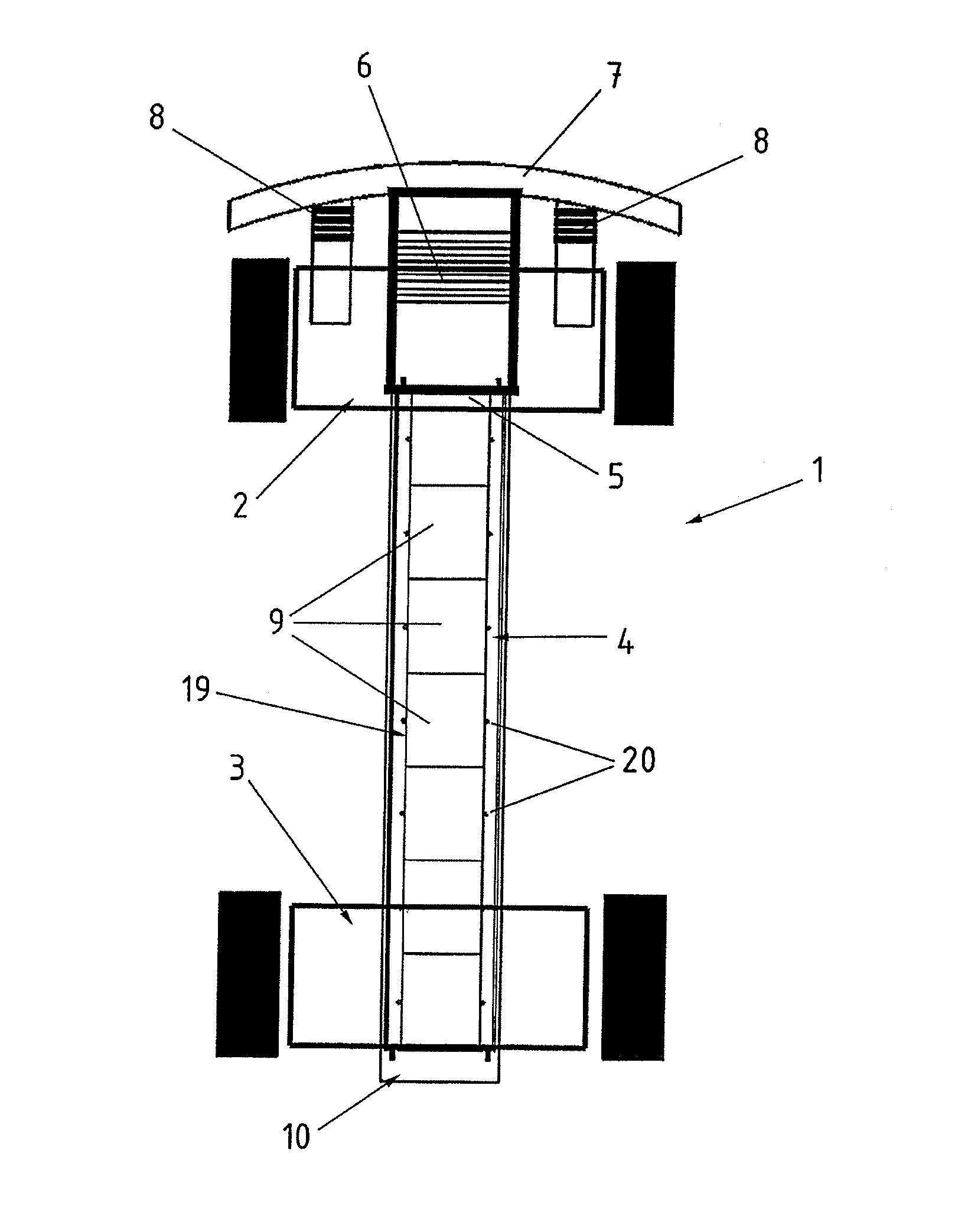
[0022]FIG. 1 is a highly simplified schematic depiction of the chassis portion of a motor vehicle 1. It can be seen that a guide 4 is disposed in the center of the motor vehicle 1, and extends longitud...


PUM


Abstract

A motor vehicle has an electric drive and at least one electrical energy storage module connected therewith. A guide extends longitudinally along the motor vehicle, and supports the storage module therein in a longitudinally displaceable manner relative to the motor vehicle.

Description

CLAIM OF PRIORITY[0001]Applicants hereby claim the priority benefits under the provisions of 35 U.S.C. §119, basing said claim of priority on German Patent Application Serial No. 10 2009 025430.7, filed Jun. 16, 2009. In accordance with the provisions of 35 U.S.C. §119 and Rule 55(b), a certified copy of the above-listed German patent application will be filed before grant of a patent.BACKGROUND OF THE INVENTION[0002]The invention relates to a motor vehicle having an electric drive, and an electric energy storage module therefor.[0003]Motor vehicles that are powered or driven, at least in part, with electrical energy (so-called hybrid drives) are among the prior art. The electrical energy for the electric drive is carried in storage modules that are also called battery packets. The weight of these storage modules is significant, particularly in motor vehicles that are driven exclusively by electricity. It is not uncommon for the storage modules to weigh 300 to 500 kg in order to att...

Claims


Application Information

Patent Timeline
Patent Type & Authority Patents(United States)
IPC IPC(8): B60L11/18B60R16/04
CPCB60K1/04B60L3/0007B60L11/1822B60L11/1877B60K2001/0427B60K2001/0438B60K2001/0477B60K2001/0494Y02T10/7005Y02T10/705Y02T10/7072Y02T90/124Y02T90/14B60L53/80B60L50/66Y02T10/70Y02T90/12
Inventor VAN DER STAPPEN, WIMKREBBERS, HARRYVAN NULAND, OLAF
Owner BENTELER AUTOMOBILTECHNIK GMBH
Why Eureka
Try Eureka