Automatic loading and unloading compartment of cable shaft disc of electric power equipment

A power equipment, automatic loading and unloading technology, applied in the direction of vehicles with loading ramps, vehicles with endless chains/loop belts, etc., can solve the problems of increasing cable laying costs, restrictions on the loading and unloading of cable reels, etc., and achieves a simple structure. , The effect of convenient loading and unloading

Inactive Publication Date: 2017-05-31
QINGDAO ZHIXIANG PATENTED TECHONLOGY DEV CO LTD
View PDF5 Cites 8 Cited by
  • Summary
  • Abstract
  • Description
  • Claims
  • Application Information

AI Technical Summary

Problems solved by technology

[0003] 1. In the process of cable laying, since the laying location is mostly determined by the direction of the cable, and most of the cable laying is done in the field, because most of the cable reels are transported by using large The transport carriage completes the transportation, and the tr

Method used


Image

  • Automatic loading and unloading compartment of cable shaft disc of electric power equipment
  • Automatic loading and unloading compartment of cable shaft disc of electric power equipment
  • Automatic loading and unloading compartment of cable shaft disc of electric power equipment

Examples


Embodiment Construction

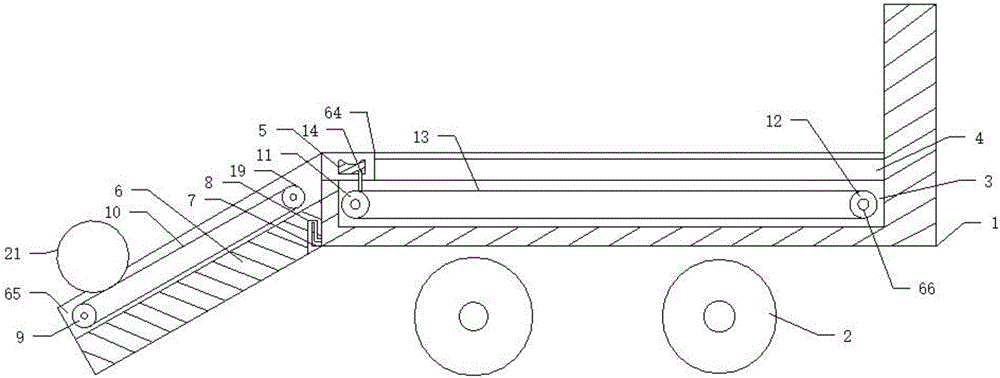
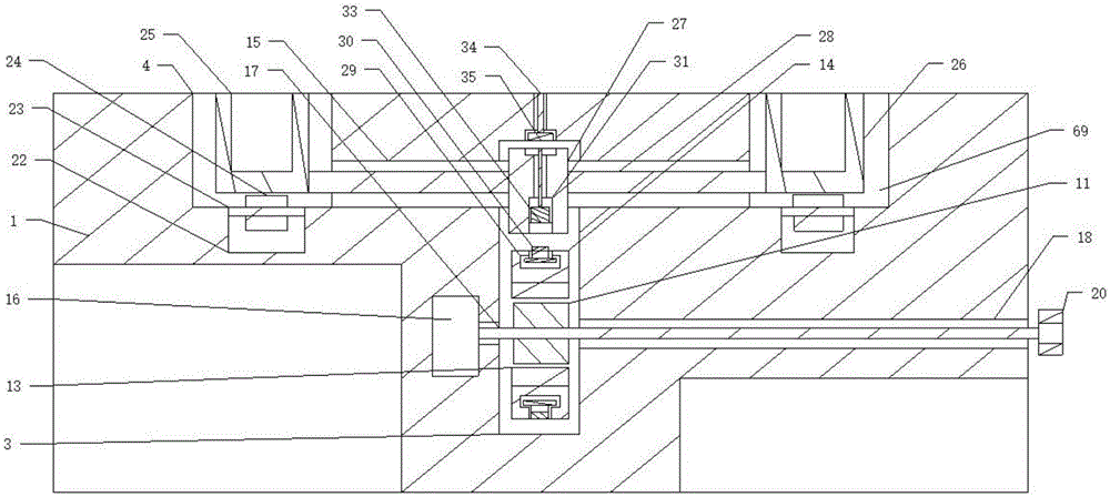
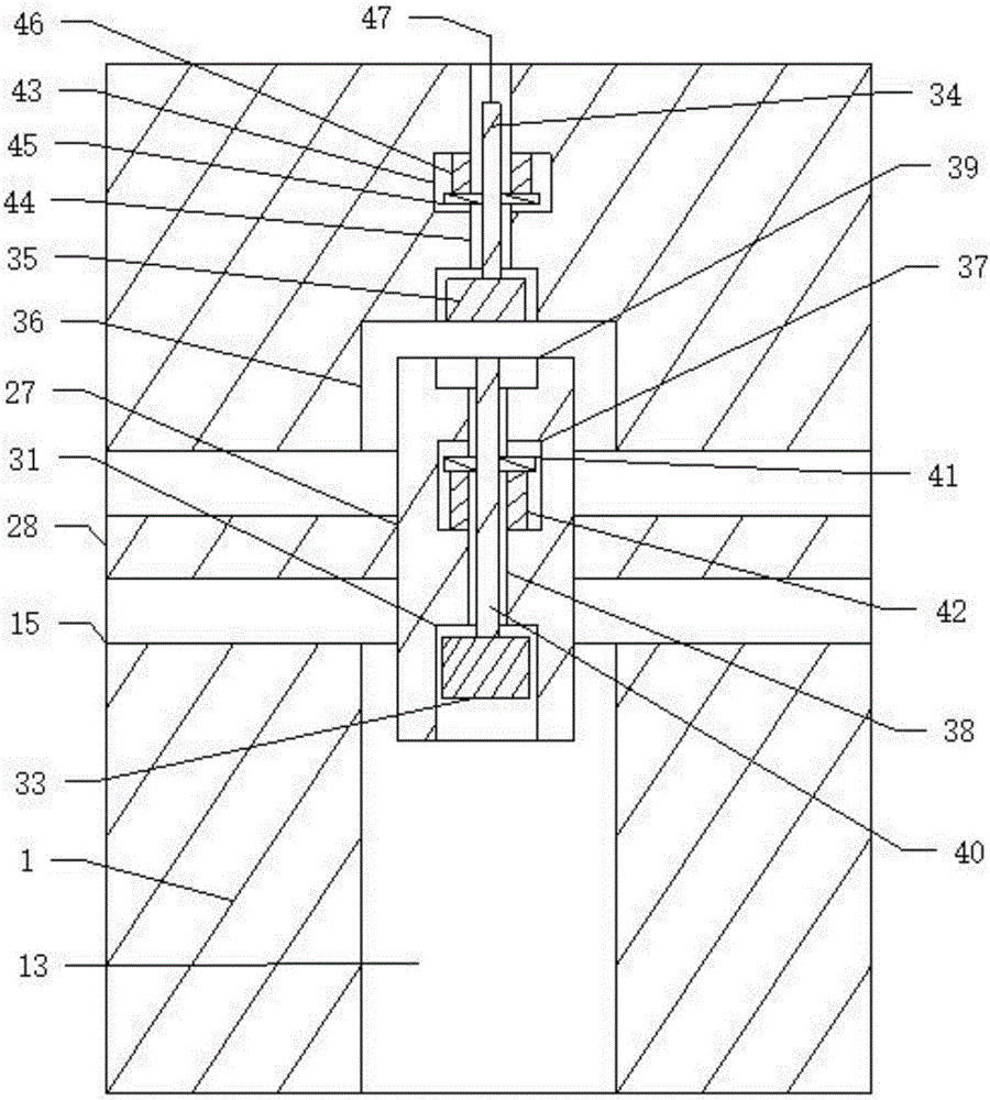
[0033] Such as Figure 1 to Figure 7 As shown, a cable reel automatic loading and unloading compartment for electric equipment includes a cable reel 21 and a compartment floor 1. Rollers 2 are provided on the compartment floor 1, and a seventh recess is provided at the end of the compartment floor 1. Groove 64, two second sliding grooves 4 corresponding to the seventh groove 64 are provided in the compartment floor 1, and a shaft disk sliding positioner 69 is arranged in the seventh groove 4, so that There is also a first chute 3 corresponding to the two second chutes 4 inside the carriage floor 1, and a seventh recess 64 in a concave shape is arranged at the end of the carriage floor 1. The carriage floor 1 is also provided with two parallel second slide grooves 4, the second slide grooves 4 are concavely arranged, and the two second slide grooves 4 are in contact with the seventh groove 64. Correspondingly communicated, a first chute 3 is also provided in the compartment fl...


PUM


Abstract

The invention discloses an automatic loading and unloading compartment of a cable shaft disc of electric power equipment. A compartment bottom plate is internally provided with two second sliding grooves which are correspondingly communicated with a seventh groove; the seventh groove is internally provided with a shaft disc sliding positioning device; the compartment bottom plate is further internally provided with a first sliding groove which corresponds to the two second sliding grooves; the shaft disc sliding positioning device comprises two shaft disc fixed blocks which slide in the second sliding grooves respectively; the shaft disc sliding positioning device further comprises a sliding positioning block which slides in the sliding grooves; each of the two shaft disc fixed blocks is connected with a third rotary shaft; each shaft disc fixed block is provided with a first shaft disc groove corresponding to the cable shaft disc; a compartment connecting plate is further connected with the end part of the compartment bottom plate and the cable shaft disc can be further driven to slide through the shaft disc fixed blocks, so that the cable shaft disc can be conveniently loaded and unloaded; the trouble caused by the fact that the cable shaft disc is loaded and unloaded by utilizing a crane is avoided.

Description

technical field [0001] The invention relates to a carriage, in particular to an automatic loading and unloading carriage for cable reels of electric equipment, in particular to an automatic loading and unloading carriage for cable reels of electric power equipment capable of automatic loading and unloading of cable reels. Background technique [0002] With the continuous improvement of living standards, it also further promotes the continuous development of the power industry. In the current power industry, cables are one of the indispensable power transmission equipment, so that cables can be used to transmit power over long distances, thereby further It can transmit electricity to thousands of households. Most of the cables are wound on the cable reels during the cable laying process, so that the transportation of the cables can be further facilitated through the cable reels. When the cables are wound on the line Due to the increase in weight after the cable reel is instal...

Claims


Application Information

Patent Timeline
IPC IPC(8): B60P1/36B60P1/43
CPCB60P1/36B60P1/43
Inventor 都函
Owner QINGDAO ZHIXIANG PATENTED TECHONLOGY DEV CO LTD
Why Eureka
Try Eureka