
Rapid dispensing machine medicine discharging device

A technology for a medicine dispensing device and a medicine dispensing machine, which is applied to storage devices, transportation and packaging, conveyor objects, etc. The effect of reduced length, increased practicality, reduced stroke

Inactive Publication Date: 2017-05-31
苏州华旸医疗器械科技有限公司
View PDF8 Cites 2 Cited by
  • Summary
  • Abstract
  • Description
  • Claims
  • Application Information

AI Technical Summary

Problems solved by technology

The medicine dispensing device of the medicine dispensing machine plays an important role in the medicine dispensing machine. Its working principle is to promote the orderly delivery of boxed medicines, and to prevent the next box of medicines from being sent out before the current medicine is taken away; Similar design, as the patent announcement number is: the invention patent of CN203153177U, discloses a medicine dispensing device of a medicine dispensing machine and a medicine dispensing machine with it, its disclosed structure is a W-shaped flipping plate, by pushing the W-shaped The flipping plate realizes blocking and dispensing, but it has the following disadvantages: 1. Using a W-shaped structure first increases the length of the entire device, and the overall volume is relatively large, and because the push block is located at the bottom of the flipping plate, the entire device is greatly increased. 2. The stroke of the driving device is relatively large, and the corresponding reserved space for equipment should also be increased.

Method used


Image

  • Rapid dispensing machine medicine discharging device
  • Rapid dispensing machine medicine discharging device
  • Rapid dispensing machine medicine discharging device

Examples


Embodiment Construction

[0016] The following will clearly and completely describe the technical solutions in the embodiments of the present invention with reference to the drawings in the embodiments of the present invention.

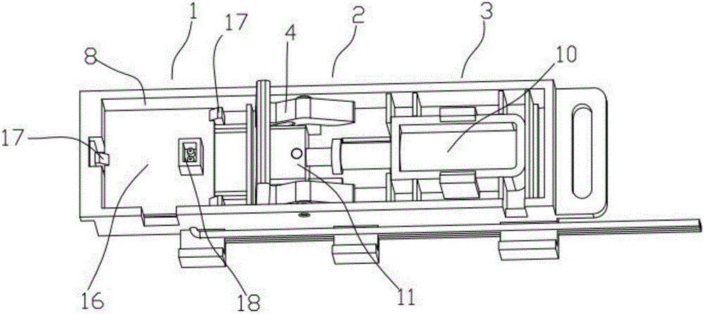
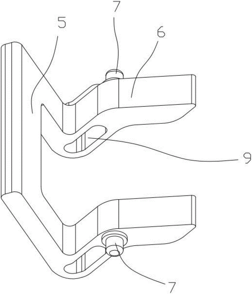
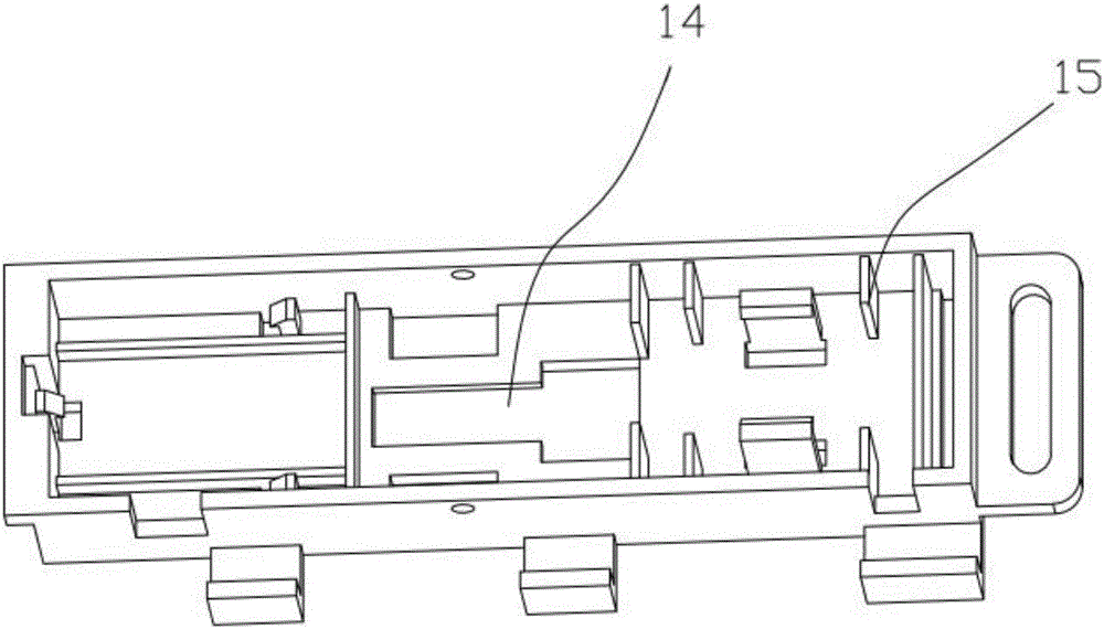
[0017] like figure 1 , figure 2 , image 3 , Figure 4 As shown, the present invention proposes a drug dispensing device for a rapid drug dispensing machine, including a fixed frame 8, in which a counting part 1, a drug retaining part 2, and a driving part 3 are sequentially arranged, and its working mode is mainly through The driving part 3 controls the work of the drug blocking part 2, wherein the drug blocking part 2 is used to limit and flip the medicine, and includes a flipping plate 4, and the flipping plate 4 includes a vertical shielding part 5 and is connected with the vertical shielding part 5. An integrally formed limiting portion 6, the side of the limiting portion 6 is connected to the fixed frame 8 through a rotating shaft 7; the limiting portion 6 is provide...


PUM


Abstract

The invention provides a rapid dispensing machine medicine discharging device. The rapid dispensing machine medicine discharging device comprises a fixing frame. A counting part, a medicine stopping part and a drive part are sequentially arranged in the fixing frame, and the counting part is used for supporting and calculating the number of medicines. The medicine stopping part is used for limiting and overturning the medicines and comprises an overturning plate. The overturning plate comprises a vertical shielding part and a limiting part integrally formed with the vertical shielding part. The side edge of the limiting part is connected with the fixing frame through a rotating shaft. The limiting part is provided with limiting grooves downwards obliquely arranged. The drive part is clamped in the limiting grooves and drives the overturning plate to rotate. The overturning plate is used in the device, the structure of the limiting grooves is used, a sliding block of the drive part is clamped in the limiting grooves of the overturning plate, and the whole overturning plate is driven to do the overturning and folding movement through the form of the limiting grooves. Compared with the prior art, the effect of dispensing is achieved, meanwhile, the stroke of the drive part is reduced, meanwhile, the height and the length of the whole device are reduced, the size of the whole device is reduced, and practicability is improved.

Description

technical field [0001] The invention relates to the field of medical equipment, in particular to a medicine dispensing device for a rapid medicine dispensing machine. Background technique [0002] The medicine dispensing machine refers to the automatic medicine taking equipment used in the medicine taking in the pharmacy. The medicine dispensing device of the medicine dispensing machine plays an important role in the medicine dispensing machine. Its working principle is to promote the orderly delivery of boxed medicines, and to prevent the next box of medicines from being sent out before the current medicine is taken away; Similar design, as the patent announcement number is: the invention patent of CN203153177U, discloses a medicine dispensing device of a medicine dispensing machine and a medicine dispensing machine with it, its disclosed structure is a W-shaped flipping plate, by pushing the W-shaped The flipping plate realizes blocking and dispensing, but it has the foll...

Claims


Application Information

Patent Timeline
Patent Type & Authority Applications(China)
IPC IPC(8): B65G1/04B65G47/88
CPCB65G1/04B65G47/8823
Inventor 陈旸天
Owner 苏州华旸医疗器械科技有限公司
Learn More