Propulsion type trace feeder

A feeder and push-type technology, which is applied in the field of push-type micro-feeders, can solve the problems of difficult adjustment of feeding amount, high feeding lower limit, uneven feeding, etc., and achieve continuous, stable and uniform feeding and material dispersion The effect of uniform and uniform feeding

Active Publication Date: 2017-05-31
HARBIN INST OF TECH
View PDF6 Cites 5 Cited by
  • Summary
  • Abstract
  • Description
  • Claims
  • Application Information

AI Technical Summary

Problems solved by technology

[0003] In order to solve the problems of the existing micro-feeders, such as high feeding lower limit, uneven feeding and difficult adjustment of feeding amount, the present invention further provides a push-type micro-feeder

Method used


Image

  • Propulsion type trace feeder

Examples


specific Embodiment approach 1

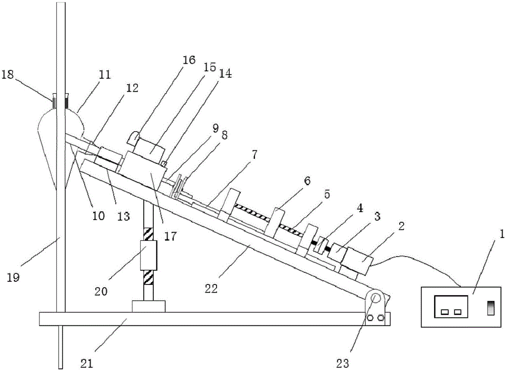
[0019] Specific implementation mode one: as figure 1 As shown, the propulsion type micro-feeder of this embodiment includes a propulsion assembly, a feeding assembly, a support assembly and a vibrating assembly, and the propulsion assembly is installed on the inclined support plate 22 of the support assembly;

[0020] The propulsion assembly includes a control box 1, a stepping motor 2, a reducer 3, a coupling 4, a slide rail 5, a slider 6 and a push rod 7; the control box 1 is electrically connected to the stepping motor 2, and the control box 1 is used to control The speed of the stepping motor 2, the stepping motor 2 is connected with the reducer 3, the reducer 3 is coaxially connected with the slide rail 5 through the coupling 4, the slide block 6 is threaded with the slide rail 5, and one end of the push rod 7 is connected with the slide rail 5 Block 6 is fixedly connected;

[0021] The support assembly includes a blanking bottle fixing clip 18, a screw adjustment suppor...

specific Embodiment approach 2

[0026] Specific implementation mode two: as figure 1 As shown, the bottom of the blanking bottle 11 in this embodiment is in an inverted conical shape, the bottom of the blanking bottle 11 is tapered from top to bottom, and the upper part of the blanking bottle 11 is hemispherical. The conical large-mouth end of the feed bottle 11 constitutes a complete blanking bottle 11 . With such a design, the top of the blanking bottle 11 is the inlet for the material carrier gas, and the bottom is tapered and extends out of a straight pipe section. Other components and connections are the same as those in the first embodiment.

specific Embodiment approach 3

[0027] Specific implementation mode three: as figure 1 As shown, the hose connector 12 in this embodiment is a silicone hose connector. With such a design, the sealing between the material storage pipe 10 and the blanking bottle 11 can be realized, and the sealing performance is good. Other compositions and connections are the same as those in Embodiment 1 or 2.


PUM


Abstract

The invention provides a propulsion type trace feeder and relates to the trace feeder. The propulsion type trace feeder solves the problems that an existing trace feeder is high in feeding lower limit, feeding is nonuniform and the feeding amount is not easy to adjust. A reducer is coaxially connected with a sliding rail through a coupling. A sliding block is in threaded connection with the sliding rail. One end of a push rod is fixedly connected with the sliding block. A slope support plate is mounted on the upper end face of a horizontal support plate through a spiral adjusting support. The lower portion of the slope support plate is hinged to one end of the horizontal support plate. A fixed stand column is vertically arranged at the other end of the horizontal support plate. A storage pipe is fixed to the upper portion of the slope support plate through a storage pipe fixing clamp. The other end of the push rod is fixedly connected with one end of a rubber tight fit push rod. The other end of the rubber tight fit push rod is inserted into one end of the storage pipe, and the rubber tight fit push rod and the storage pipe are tightly connected. The other end of the storage pipe is inserted into the center of a falling bottle. The storage pipe is wrapped with a support fixing frame, and the support fixing frame is fixed to the slope support plate. The propulsion type trace feeder is used for trace feeding.

Description

technical field [0001] The invention relates to a micro-feeder, in particular to a push-type micro-feeder. Background technique [0002] For micro-feeding equipment, there are currently screw-type, wheel-type and roller-type micro-feeders. The lower limit of the feeding amount of the existing micro-feeders is several kg / h, and there are problems such as a higher lower limit of feeding, and The problem of uneven material and difficult adjustment of feeding amount. Contents of the invention [0003] In order to solve the problems of the existing micro-feeders, such as high feeding lower limit, uneven feeding and difficult adjustment of feeding amount, the present invention further provides a push-type micro-feeder. [0004] The technical scheme that the present invention takes for solving the problems of the technologies described above is: [0005] The push-type micro-feeder of the present invention includes a push assembly, a feed assembly, a support assembly and a vibra...

Claims


Application Information

Patent Timeline
Patent Type & Authority Applications(China)
IPC IPC(8): B65G47/82B65G65/32
CPCB65G47/82B65G65/32
Inventor 赵来福吴少华高建民杜谦徐力赵广播栾积毅
Owner HARBIN INST OF TECH
Why Eureka
Try Eureka