

Carrier tape coiling device
A technology of winding device and carrier tape, which is applied in the direction of transportation and packaging, thin material handling, and delivery of filamentous materials, etc., can solve the problems of low efficiency, incomplete automation, and high labor intensity of workers, so as to save costs, The effect of reducing the labor intensity of workers and improving work efficiency
- Summary
- Abstract
- Description
- Claims
- Application Information
AI Technical Summary
Problems solved by technology
Method used
Image

Examples
Embodiment Construction
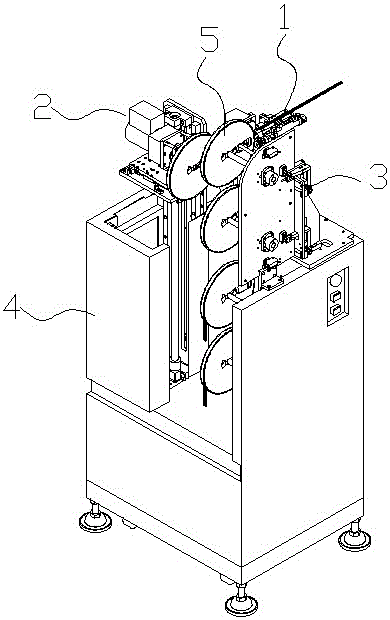
[0033] see Figure 1-Figure 14 , The present invention relates to a carrier tape multi-disc rewinding system, which includes a carrier tape feeding device 1 , a carrier tape rewinding device 2 and a reel storage device 3 . The carrier tape rewinding device 2 is used for rewinding the carrier tape on the carrier tape feeding device 1, and the reel storage device 3 is used for storing the empty reel before rewinding and the full reel after rewinding. The device 1 is used to send the carrier tape head to the empty tray on the carrier tape winding device 2 . The carrier tape winding device 2 and the tray storage device 3 are installed in the same case 4 , and a frame plate 401 arranged longitudinally is arranged in the case 4 .
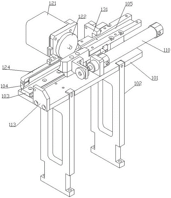
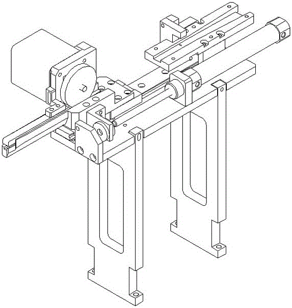
[0034] The carrier tape feeding device 1 includes a track assembly, a feeding assembly and a transmission assembly;
[0035] The track assembly includes a track installation base plate 101, a track installation base plate support foot 102, a moving trac...
PUM
 Abstract
Description
Claims
Application Information