
Solid-liquid separation device under pressure-holding condition of drilling construction mud in pressurized water formation

A construction mud and solid-liquid separation technology, applied in earthwork drilling, wellbore/well components, flushing wellbore, etc., can solve problems such as unstable mud pressure, difficulty in forming mud and formation water and soil pressure balance, sand gushing, etc. To achieve the effect of ensuring normal advancement, reducing soil erosion, and avoiding disturbance effects

Active Publication Date: 2019-10-15
TIANDI SCI & TECH CO LTD +1
View PDF4 Cites 0 Cited by
  • Summary
  • Abstract
  • Description
  • Claims
  • Application Information

AI Technical Summary

Problems solved by technology

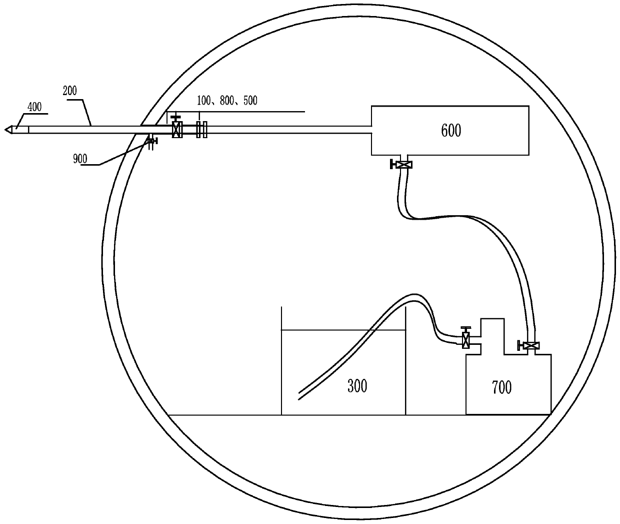
Construction under this drilling device has the following disadvantages: 1) The mud pressure in the hole is unstable, and it is difficult to form a balance of water and soil pressure between the mud and the formation; 2) The drilling slag can only rely on the opening of the orifice pipe bypass valve, It is easy to cause water gushing and sand gushing

Method used


Image

  • Solid-liquid separation device under pressure-holding condition of drilling construction mud in pressurized water formation
  • Solid-liquid separation device under pressure-holding condition of drilling construction mud in pressurized water formation
  • Solid-liquid separation device under pressure-holding condition of drilling construction mud in pressurized water formation

Examples


Embodiment Construction

[0028] In order to clearly illustrate the solutions in the present invention, preferred embodiments are given below and detailed descriptions are given in conjunction with the accompanying drawings.

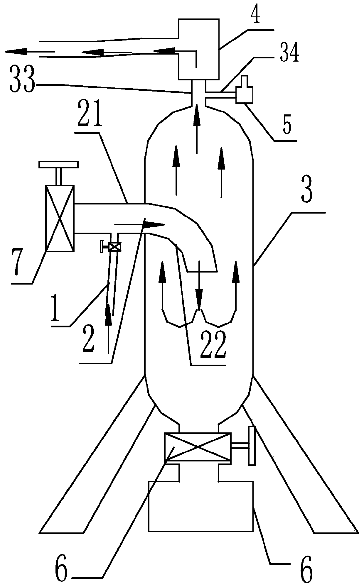
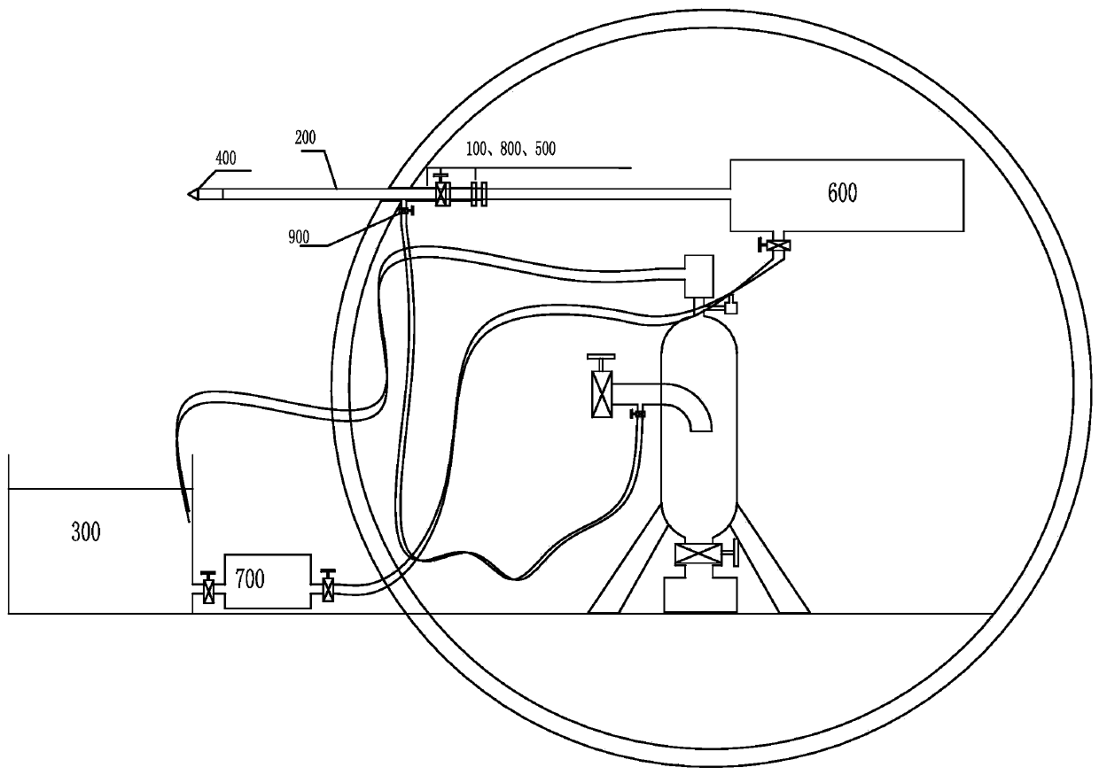
[0029] Such as figure 2 As shown, the solid-liquid separation device in this embodiment includes a first pipeline 1, a second pipeline 2, a slurry tank 3 and an adjustable automatic pressure relief valve 4 under the pressure-holding condition of the drilling construction mud in the pressurized water formation; The inlet of the pipeline 1 is connected with the orifice pipe 100, the outlet of the first pipeline 1 is connected with the inlet of the second pipeline 2; the outlet of the second pipeline 2 is connected with the inlet of the slurry storage tank 3 The adjustable automatic pressure relief valve 4 is installed at the mud outlet on the top of the mud storage tank 3 .

[0030] The drill pipe 200 passes through the pipe hole of the orifice pipe 100 , that is, the first pipe ...


PUM


Abstract

The invention discloses a solid-liquid separation device under slurry pressure maintaining conditions for confined water stratum drilling construction. The solid-liquid separation device comprises a first pipeline, a second pipeline, a slurry storage tank, an adjustable automatic pressure relief valve and slag storage tanks. An inlet of the first pipeline is communicated with an orifice pipe, and an outlet of the first pipeline is communicated with a lateral inlet of the second pipeline; one end of the second pipeline is connected with a valve, and the other end of the second pipeline is connected with an downward 90-degree elbow; an outlet of the elbow of the second pipeline deeply extends into a cavity of the slurry storage tank and is communicated with an inlet of the slurry storage tank, and the adjustable automatic pressure relief valve is mounted at a slurry outlet in the top of the slurry storage tank; the slag storage tanks are hermetically mounted at slag discharge positions at the bottom of the slurry storage tank via valves. The solid-liquid separation device under the slurry pressure maintaining conditions for the confined water stratum drilling construction has the advantages that the solid-liquid separation device is applied to drilling construction procedures carried out in confined water strata, accordingly, disturbance influence of drilling construction on the original strata can be relieved or prevented by water and soil pressure balance between slurry and the strata, water and soil loss can be reduced, and normal drilling propulsion can be guaranteed.

Description

technical field [0001] The invention relates to equipment in the technical field of drilling construction in pressurized water formations, in particular to a solid-liquid separation device under pressure-maintaining conditions in a mud circulation system for drilling construction in pressurized water formations. Background technique [0002] In the construction of municipal tunnels, deep foundation pits and subways, part of the working face of the drilling construction is located below the groundwater level or the opening position is located in the confined water stratum. When no measures are taken for construction, accidents such as water gushing and sand gushing often occur. Cause serious water and soil erosion in the stratum, and even ground subsidence, damaging the surrounding structures. Therefore, in the process of horizontal drilling in confined water formations, the balance of water and soil pressure between the mud and the formation can slow down or avoid the impact...

Claims


Application Information

Patent Timeline
Patent Type & Authority Patents(China)
IPC IPC(8): E21B21/06
Inventor 李方政崔灏高伟陈红蕾许舒荣郭垒崔兵兵姜国静张绪忠石红伟叶玉西王恒王磊张基伟王楷温汉宏高玉琪刘晓敏
Owner TIANDI SCI & TECH CO LTD
Learn More