Anti-icing system of engine

An anti-icing system and engine technology, which is applied in the direction of machines/engines, mechanical equipment, gas turbine devices, etc., can solve the problems of inability to guarantee the effect of impact heat exchange heating, reduced surface integrity of anti-icing holes, and poor anti-icing ability of caps, etc. Problems, to achieve the effect of ensuring strength, ensuring heat exchange effect, and large hot air flow

Active Publication Date: 2017-05-31
AECC SHENYANG ENGINE RES INST
View PDF6 Cites 16 Cited by
  • Summary
  • Abstract
  • Description
  • Claims
  • Application Information

AI Technical Summary

Problems solved by technology

[0004] This anti-icing method has the following disadvantages: 1. Due to the particularity of the inner cavity structure of the rectifying strut, the impact hole is far away from the impact target surface, and the impact heat transfer coefficient is greatly affected by the distance between the impact hole and the impact target surface. Therefore, it is impossible to ensure that the impact heat transfer can achieve the optimal heat

Method used


Image

  • Anti-icing system of engine

Examples


Embodiment Construction

[0018] In order to make the objectives, technical solutions and advantages of the present invention clearer, the technical solutions in the embodiments of the present invention will be described in more detail below in conjunction with the drawings in the embodiments of the present invention. In the drawings, the same or similar reference numerals denote the same or similar elements or elements having the same or similar functions throughout. The described embodiments are some, but not all, embodiments of the invention. The embodiments described below by referring to the figures are exemplary and are intended to explain the present invention and should not be construed as limiting the present invention. Based on the embodiments of the present invention, all other embodiments obtained by persons of ordinary skill in the art without creative efforts fall within the protection scope of the present invention. Embodiments of the present invention will be described in detail below ...


PUM


Abstract

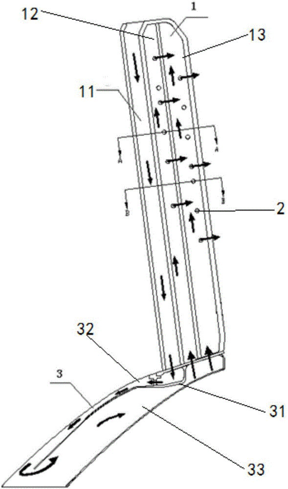
The invention discloses an anti-icing system of an engine. The anti-icing system of the engine comprises a rectifying supporting plate and a rectifying cover hood. The rectifying supporting plate comprises a first cavity, a second cavity and a third cavity. The first cavity, the second cavity and the third cavity are adjacent to one another. Exhaust holes are formed in the second cavity and the third cavity of the rectifying supporting plate. The rectifying cover hood communicates with the rectifying supporting plate. A partition plate is arranged in the rectifying cover hood. The rectifying cover hood is divided into a first partitioned cavity and a second partitioned cavity through the rectifying cover hood. The first partitioned cavity communicates with the second partitioned cavity. The first partitioned cavity communicates with the first cavity. The second partitioned cavity communicates with the second cavity and the third cavity. According to the anti-icing system of the engine, ice prevention is conducted through the pipe flow heat exchange mode, the hot air is high in temperature and flow, the heat exchange coefficient of the supporting plate leading edge and the side wall of the first cavity of the rectifying supporting plate is guaranteed, and the heat exchange effect from the top to the bottom of the whole first cavity of the rectifying supporting plate is guaranteed.

Description

technical field [0001] The invention relates to the technical field of engine anti-icing, in particular to an engine anti-icing system. Background technique [0002] When the aircraft flies under the condition of temperature below zero and small Mach number, due to the existence of supercooled water droplets in the air, the surface of the engine inlet rectifying strut plate and the cowling cover will be icy. The icing of the rectifying struts and the cowl will change the aerodynamic shape of the struts and the cowl, resulting in a decrease in aerodynamic performance, and at the same time, the icing of the struts will reduce the air intake area. In addition, the ice accumulation and falling off of the support plate and the cap may injure or damage the core components of the engine, which will have a great impact on the performance of the engine and flight stability. Therefore, it is necessary to carry out an anti-icing structure design on the engine inlet rectifying strut an...

Claims


Application Information

Patent Timeline
IPC IPC(8): F02C7/047
CPCF02C7/047
Inventor 龚欢李云单苗海丰沈毅
Owner AECC SHENYANG ENGINE RES INST
Why Eureka
Try Eureka