Vacuumizing system and method

A vacuum pumping system and vacuum pumping technology, applied in the field of vacuum pumping systems, can solve problems such as not being able to meet requirements, and achieve the effects of saving pumping time, reducing costs, and quickly pumping air

Inactive Publication Date: 2017-05-31
SHENYANG SCI INSTR RES CENT CHINESE ACAD OF SCI
View PDF7 Cites 4 Cited by
  • Summary
  • Abstract
  • Description
  • Claims
  • Application Information

AI Technical Summary

Problems solved by technology

This cannot meet the requirements in some applications that need to obtain the required vacuum degree more quickly, especially high vacuum degree

Method used


Image

  • Vacuumizing system and method
  • Vacuumizing system and method

Examples


Embodiment Construction

[0028] Preferred embodiments of the present invention will be described in detail below with reference to the accompanying drawings, so as to better understand the purpose, features and advantages of the present invention. It should be understood that the embodiments shown in the drawings are not intended to limit the scope of the present invention, but only to illustrate the essence of the technical solutions of the present invention.

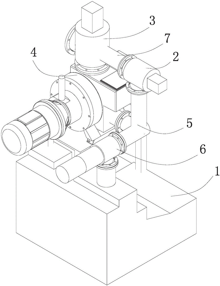
[0029] like figure 1 As shown, the vacuum system includes a backing pump 1, a main pump 4, a pre-pump valve 2 and a main valve 3, wherein the main valve 3 is provided with an inlet, a pre-pump and an outlet, and the inlet of the main valve 3 is arranged on the The vacuum port on the vacuum chamber (not shown) to be evacuated is communicated, the pre-extraction port of the main valve 3 is communicated with the inlet of the pre-evacuation valve 2, and the outlet of the main valve 3 is communicated with the suction port of the main pump 4. The s...


PUM


Abstract

The invention discloses a vacuumizing system. The vacuumizing system is used for vacuumizing a vacuum chamber and comprises a backing pump, a main pump, a pre-pumping valve and a main valve, wherein the main valve is provided with an inlet, a pre-pumping port and an outlet; the inlet of the main valve communicates with a vacuumizing port of the vacuum chamber; the pre-pumping port of the main valve communicated with an inlet of the pre-pumping valve; the outlet of the main valve communicates with an extraction opening of the main pump; and an extraction opening of the backing pump simultaneously and directly communicates with an exhaust port of the main pump and an outlet of the pre-pumping valve through a tee coupling. Through the vacuumizing system, the vacuum chamber can reach the required vacuum degree in a quite short time.

Description

technical field [0001] The invention relates to vacuum equipment, in particular to a vacuum system for vacuuming a vacuum chamber. Background technique [0002] A conventional vacuum system usually includes a backing pump, a main pump, a backing valve, a pre-pumping valve and a main valve, wherein the backing pump is connected to the pre-pumping port of the vacuum chamber through a pipeline, and the above-mentioned pre-pumping valve is arranged on the pipeline . The suction port of the main pump is connected to the vacuum port of the vacuum chamber through the main valve, and the exhaust port of the main pump is connected to the exhaust port of the backing pump through a pipeline, and the backing pump is arranged on the pipeline. The working process of the conventional vacuum pumping system is as follows: first close the fore-stage valve and the main valve, turn on the fore-stage pump, open the pre-pumping valve, when the vacuum chamber reaches a predetermined vacuum degree...

Claims


Application Information

Patent Timeline
Patent Type & Authority Applications(China)
IPC IPC(8): F04B37/14F04B39/10F04B41/06
CPCF04B37/14F04B39/10F04B41/06
Inventor 王宏宇黄晓霞张国栋
Owner SHENYANG SCI INSTR RES CENT CHINESE ACAD OF SCI
Why Eureka
Try Eureka