Infiltration method and device for large thin-wall part

A large-scale thin-walled parts, impregnation technology, applied in the field of impregnation, thin-walled parts production, can solve the waste of impregnating liquid, complex structure, time-consuming and other problems, to achieve short vacuuming time, small volume, low cost Effect

Pending Publication Date: 2022-05-24
烟台路通精密科技股份有限公司
View PDF0 Cites 0 Cited by
  • Summary
  • Abstract
  • Description
  • Claims
  • Application Information

AI Technical Summary

Problems solved by technology

However, the currently commonly used vacuum impregnation equipment has a complex structure and high cost, and is suitable for batch impregnation of small-sized products. For large thin-walled parts, due to space constraints, usually only one or two products can be impregnated at a time, and It is necessary to vacuum the entire vacuum impregnation tank, and then inhale a large amount of impregnation liquid to infiltrate the product, which takes a long time, is inefficient, and wastes the impregnation liquid. Therefore, an impregnation method and device for large thin-walled parts are now needed. help to solve the above problems

Method used


Image

  • Infiltration method and device for large thin-wall part
  • Infiltration method and device for large thin-wall part
  • Infiltration method and device for large thin-wall part

Examples


Embodiment 1

[0035] Example 1: Impregnation of large thin-walled parts

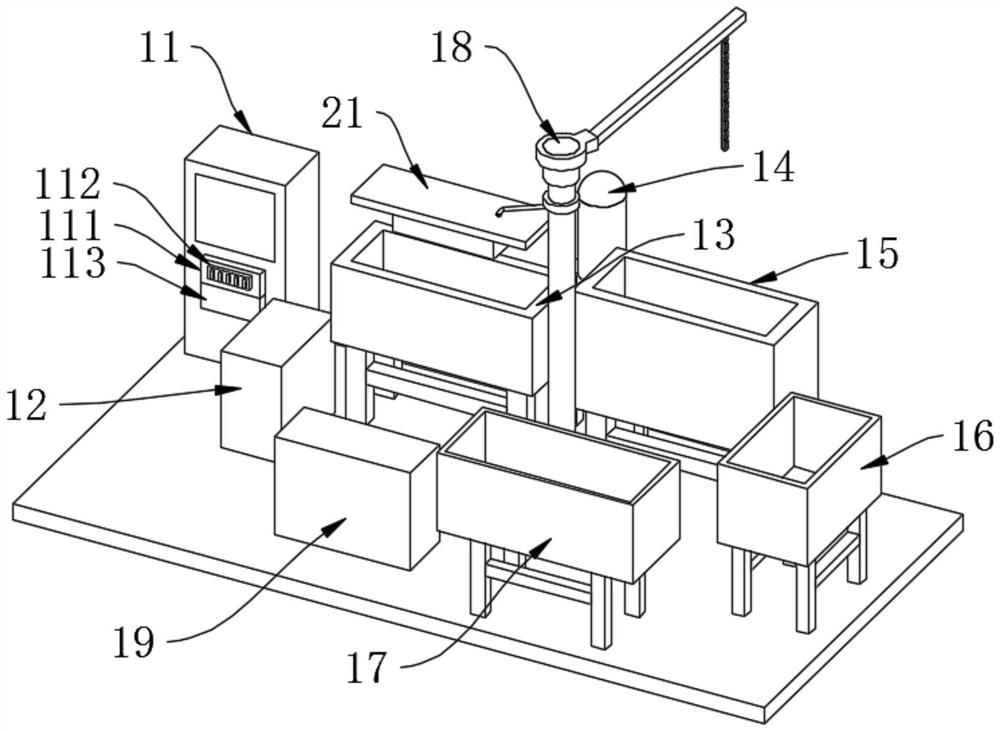
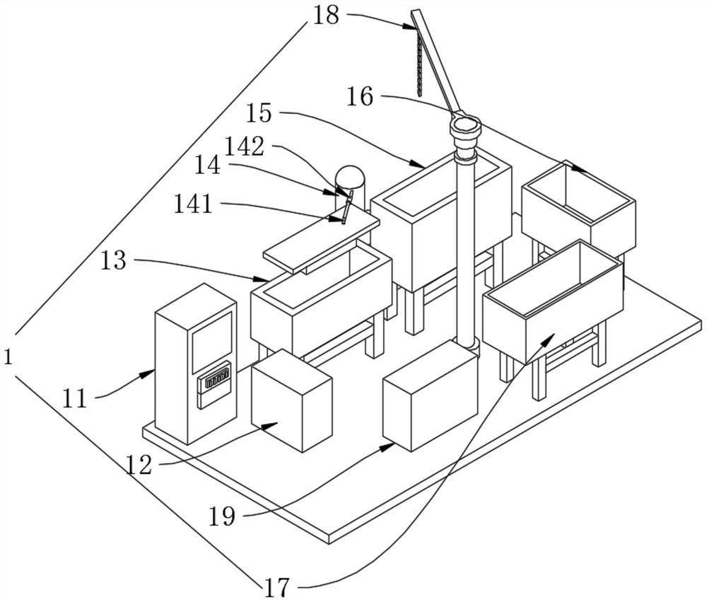
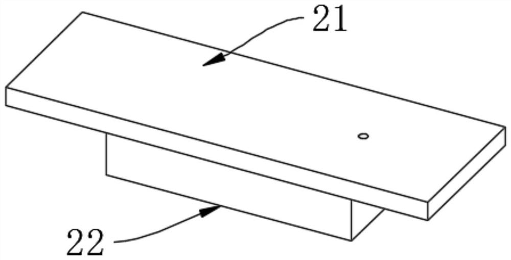
[0036]Including main assembly 1, main assembly 1 includes electric control cabinet 11, clamping table 12, vacuum sealing tooling assembly 2, impregnation tank 13, vacuum pump 14, air shower deliquoring tank 15, cleaning tank 16, hot water curing tank 17. Cantilever crane 18 and processing table 19, vacuum sealing tooling assembly 2 includes vacuum sealing plate 21 and adsorption seat 22, adsorption seat 22 is installed on the bottom of vacuum sealing plate 21 by bolts, electric control cabinet 11, clamping work The stage 12, the impregnation tank 13 and the air shower deliquoring tank 15 are arranged in sequence, the vacuum pump 14 is arranged on one side of the impregnation tank 13, the cleaning tank 16 is arranged on the side of the air shower deliquoring tank 15, and the hot water curing tank 17 is arranged on the cleaning tank. 16 side, the processing table 19 is set on the hot water curing pool 17 side, the canti...

Embodiment 2

[0044] Example 2: Casting Stability Monitoring

[0045] Including main assembly 1, main assembly 1 includes electric control cabinet 11, clamping table 12, vacuum sealing tooling assembly 2, impregnation tank 13, vacuum pump 14, air shower deliquoring tank 15, cleaning tank 16, hot water curing tank 17. Cantilever crane 18 and processing table 19, vacuum sealing tooling assembly 2 includes vacuum sealing plate 21 and adsorption seat 22, adsorption seat 22 is installed on the bottom of vacuum sealing plate 21 by bolts, electric control cabinet 11, clamping work The stage 12, the impregnation tank 13 and the air shower deliquoring tank 15 are arranged in sequence, the vacuum pump 14 is arranged on one side of the impregnation tank 13, the cleaning tank 16 is arranged on the side of the air shower deliquoring tank 15, and the hot water curing tank 17 is arranged on the cleaning tank. 16 side, the processing table 19 is set on the hot water curing pool 17 side, the cantilever cran...


PUM


Abstract

The invention discloses an infiltration method and device for a large thin-walled workpiece, and belongs to the related technical field of thin-walled workpiece production.The device comprises a main body assembly, and the main body assembly comprises an electric control cabinet, a clamping workbench, a vacuum plugging tool assembly, an infiltration pool, a vacuum pump, an air shower liquid removal pool, a cleaning pool, a hot water curing pool, a cantilever crane and a treatment workbench; the vacuum plugging tool assembly comprises a vacuum plugging plate and an adsorption base, the adsorption base is installed at the bottom of the vacuum plugging plate through bolts, the electric control cabinet, the clamping workbench, the infiltration pool and the air shower liquid removal pool are sequentially arranged, the vacuum pump is arranged on one side of the infiltration pool, the cleaning pool is arranged on one side of the air shower liquid removal pool, and the hot water curing pool is arranged on one side of the cleaning pool. The processing workbench is arranged on one side of the hot water curing pool, the cantilever crane is arranged in the center of the main body assembly, a power source, a switch group and a control unit are arranged on the electric control cabinet, and the switch group and the control unit are connected with the power source through wires.

Description

technical field [0001] The invention relates to an infiltration method, in particular to an infiltration method and device for large thin-walled parts, and belongs to the technical field related to the production of thin-walled parts. Background technique [0002] Impregnation is to infiltrate the sealing medium (usually a low-viscosity liquid) into the micropores (slits) through natural infiltration (ie, micropore self-priming), vacuuming and pressure, etc., fill the gaps, and then pass through natural (room temperature) methods. ), cooling or heating to solidify the sealing medium in the gap to achieve the function of sealing the gap. During the low-pressure casting process, defects such as micropores and blisters will occur due to the solidification volume shrinkage of the metal solution, impurities or gas residues. Defective castings may leak liquid and gas and become unqualified products. Especially for large thin-walled parts, if they are scrapped due to leakage, it w...

Claims


Application Information

Patent Timeline
Patent Type & Authority Applications(China)
IPC IPC(8): B22D31/00
CPCB22D31/005
Inventor 陈国诗李淑萍张硕夏克莹鹿志东刘培德
Owner 烟台路通精密科技股份有限公司
Why Eureka
Try Eureka