Check patentability & draft patents in minutes with Patsnap Eureka AI!

Direction-adjustable rotary driving device

A technology of slewing drive and direction adjustment, which is applied to transmission parts, belts/chains/gears, mechanical equipment, etc., and can solve the undiscovered technology of slewing drive device direction adjustment, photovoltaic support connecting pipes that cannot be installed, installed and used. Limitations and other issues, to achieve the effect of meeting performance requirements, facilitating installation, and saving cost and time

Pending Publication Date: 2017-05-31
WUXI KEANERGY PHOTOVOLTAIC EQUIP CO LTD
View PDF9 Cites 0 Cited by
  • Summary
  • Abstract
  • Description
  • Claims
  • Application Information

AI Technical Summary

Problems solved by technology

[0002] Due to the installation and use of traditional slewing drives will be limited by the site
When the slewing drive device is used in the field of solar photovoltaics, when the ground of the site is uneven or dislocated, the connecting pipe of the photovoltaic support cannot be installed on the slewing drive device, and manual leveling and alignment are required, which makes the installation of the photovoltaic support difficult, time-consuming and laborious
[0003] In the prior art, there is no technology to adjust the direction of the slewing drive

Method used


Image

  • Direction-adjustable rotary driving device
  • Direction-adjustable rotary driving device
  • Direction-adjustable rotary driving device

Examples


Embodiment

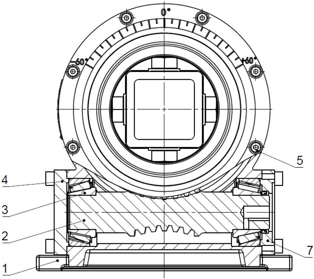
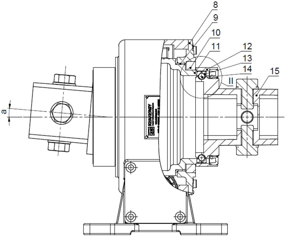
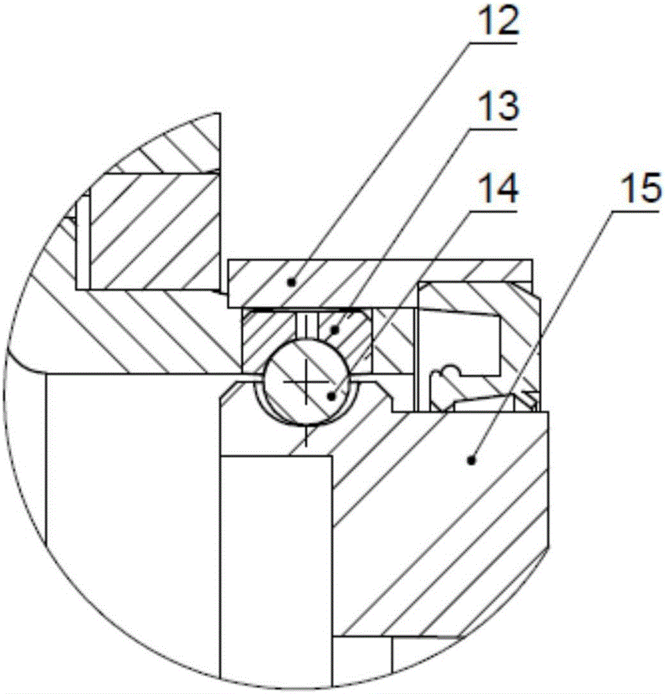
[0029] like Figure 1-6 Shown is the overall and partial structural schematic diagram of the adjustable direction rotary driving device of the present invention. The adjustable rotary drive device includes a base 1, a worm 2, a bearing 3, an end cover 4, a connecting bolt 5, a motor adjustment block 7, a cover plate 8, a sliding bearing 9, an oil seal 10, a gear top plate 11 and left and right sets respectively A group of steering mechanisms, each group of steering mechanisms includes a heat collar 12, a number of steel ball bowls 13, a number of steel balls 14 and a transmission flange 15. The base 1 includes a shaft shell and a seat ring. The axis line of the shaft shell and the axis line of the seat ring are perpendicular to each other in space; the worm 2 is positioned in the shaft shell of the base 1 through the bearing 3; 9 is arranged in the space formed by the seat ring of the base 1 and the cover plate, and the gear top plate 11 is engaged with the worm 2. The motor...


PUM


Abstract

The invention discloses a direction-adjustable rotary driving device. The direction-adjustable rotary driving device comprises a base, a worm, a bearing, a cover plate, a gear top plate, a sliding bearing and a direction adjusting mechanism; the direction adjusting mechanism comprises a plurality of ball bowls, a plurality of balls and a driving flange; the worm is installed in the base through the bearing; the gear top plate is pressed into the base and the cover plate through the sliding bearing and engaged with the worm; the gear top plate is provided with a plurality of holes, and the multiple ball bowls are arranged in the holes of the gear top plate correspondingly; a plurality of arc-shaped grooves are formed in the top surface of the front portion of the driving flange and correspond to the ball bowls in a one-to-one mode; and the multiple balls are arranged in spaces formed by the ball bowls and the arc-shaped grooves in a matched mode correspondingly, and a gap is formed between each ball and the side wall of the corresponding arc-shaped groove. Through the direction-adjustable rotary driving device, direction adjusting of the rotary driving device is achieved.

Description

technical field [0001] The invention relates to the technical field of slewing drive equipment, in particular to an adjustable slewing drive device. Background technique [0002] The installation and use of the traditional slewing drive will be limited by the site. When the slewing drive device is used in the field of solar photovoltaics, when the ground of the site is uneven or dislocated, the connecting pipe of the photovoltaic support cannot be installed on the slewing drive device, and manual leveling and alignment are required, which makes the installation of the photovoltaic support difficult, time-consuming and laborious . [0003] In the prior art, there is no technique for adjusting the direction of the slewing drive. Contents of the invention [0004] The object of the present invention is to provide a direction-adjustable rotary driving device. [0005] To achieve the above object, the present invention adopts the following content: [0006] A direction-adju...

Claims


Application Information

Patent Timeline
Patent Type & Authority Applications(China)
IPC IPC(8): F16H57/039F16H57/023F16H57/022
CPCF16H57/022F16H57/023F16H57/039F16H2057/0213
Inventor 王文斌
Owner WUXI KEANERGY PHOTOVOLTAIC EQUIP CO LTD
Features
  • R&D
  • Intellectual Property
  • Life Sciences
  • Materials
  • Tech Scout
  • Unparalleled Data Quality
  • Higher Quality Content
  • 60% Fewer Hallucinations
Learn More