Detected lens mounting and adjusting method and device for spherical lens surface shape absolute calibration.

A spherical lens and lens technology, applied in the direction of using optical devices, measuring devices, instruments, etc., can solve the problem of large optical axis error of the lens

Active Publication Date: 2017-05-31
CHANGCHUN INST OF OPTICS FINE MECHANICS & PHYSICS CHINESE ACAD OF SCI
View PDF6 Cites 7 Cited by
  • Summary
  • Abstract
  • Description
  • Claims
  • Application Information

AI Technical Summary

Problems solved by technology

In fact, using this method to determine the coordinate position of the lens optical axis in the surface shape detection results ignores the influence of the lens

Method used


Image

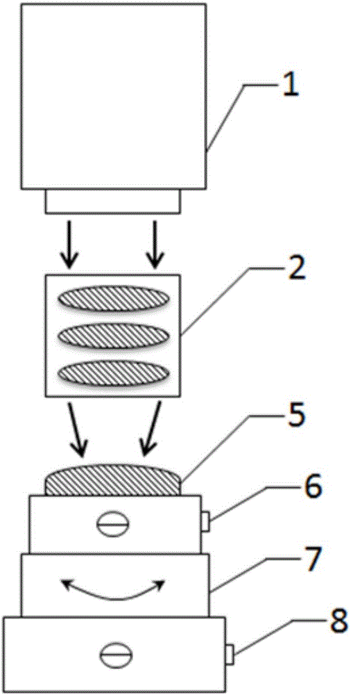
  • Detected lens mounting and adjusting method and device for spherical lens surface shape absolute calibration.
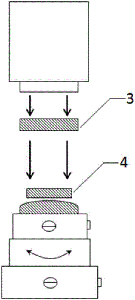
  • Detected lens mounting and adjusting method and device for spherical lens surface shape absolute calibration.
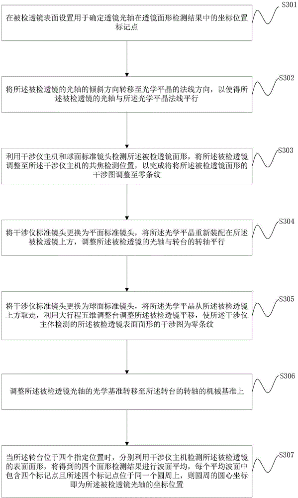
  • Detected lens mounting and adjusting method and device for spherical lens surface shape absolute calibration.

Examples


Embodiment Construction

[0041] In order to enable those skilled in the art to better understand the solutions of the present invention, the following will clearly and completely describe the technical solutions in the embodiments of the present invention in conjunction with the drawings in the embodiments of the present invention. Obviously, the described embodiments are only It is an embodiment of a part of the present invention, but not all embodiments. Based on the embodiments of the present invention, all other embodiments obtained by persons of ordinary skill in the art without making creative efforts shall fall within the protection scope of the present invention.

[0042] The terms "first", "second", "third", "fourth", etc. (if any) in the description and claims of the present invention and the above drawings are used to distinguish similar objects and not necessarily Describe a specific order or sequence. It is to be understood that the terms so used are interchangeable under appropriate cir...


PUM


Abstract

The invention discloses a detected lens mounting and adjusting method for spherical lens surface shape absolute calibration. In a spherical lens surface shape error absolute calibration process, the coordinate position of an optical axis of a detected lens in a surface shape interference detection result can be accurately positioned, so important guarantee is provided for high precision correction on a surface shape error of the detected lens, influence of a two-surface surface inclination processing error and a lens centering processing error of a traditional lens in the prior art is avoided, a problem that the coordination position of an optical axis of a detected lens in the surface shape detection result can not be accurately positioned in the prior art is solved. The invention further provides a detected lens mounting and adjusting device for spherical lens surface shape absolute calibration.

Description

technical field [0001] The invention relates to the technical field of optical interference measurement, in particular to a method and device for assembling and adjusting an inspected mirror used for absolute calibration of spherical lens surface shape. Background technique [0002] Modern lithography technology requires that the root mean square error of optical components such as planar, spherical and aspheric surfaces of the lithography objective lens system reach sub-nanometer level. Today's cutting-edge optical processing and inspection technology can easily support spherical mirrors and flat mirrors to achieve sub-nanometer surface accuracy. However, the high-precision surface shape processing and detection technology of aspheric mirrors is still relatively difficult and complicated, and the zero compensation mirror method is the most commonly used technology to achieve high-precision detection of aspheric mirror surface shape errors. The zero compensation mirror used...

Claims


Application Information

Patent Timeline
IPC IPC(8): G01B11/24
CPCG01B11/2441
Inventor 苗亮张文龙刘钰马冬梅金春水
Owner CHANGCHUN INST OF OPTICS FINE MECHANICS & PHYSICS CHINESE ACAD OF SCI
Why Eureka
Try Eureka