Method for correcting deviation of coordinate axis of inertial sensor

An inertial sensor and sensor technology, applied in the field of sensors, can solve problems such as coordinate axis offset, and achieve an effect that is easy to promote

Active Publication Date: 2017-05-31
ZHEJIANG UNIV
View PDF4 Cites 3 Cited by
  • Summary
  • Abstract
  • Description
  • Claims
  • Application Information

AI Technical Summary

Problems solved by technology

[0003] However, due to the small size of the inertial sensor, the coordinate axis deviation often occurs during the production and welding process. When it is placed on the measured object, it often deviates from the ideal position due to factors such as the uneven surface of the measured object. Therefore, Correcting the coordinate axis of the inertial sensor is of great significance for improving the measurement accuracy
At present

Method used


Image

  • Method for correcting deviation of coordinate axis of inertial sensor
  • Method for correcting deviation of coordinate axis of inertial sensor
  • Method for correcting deviation of coordinate axis of inertial sensor

Examples


Embodiment Construction

[0042] The present invention will be further described below in conjunction with the accompanying drawings for better understanding. The technical features of the present invention can be combined with each other on the premise that they do not conflict with each other, and do not constitute a limitation.

[0043] Taking the use of inertial sensors to measure the acceleration and angular velocity of the calf when a person is walking as an example, the specific implementation process of the present invention is as follows:

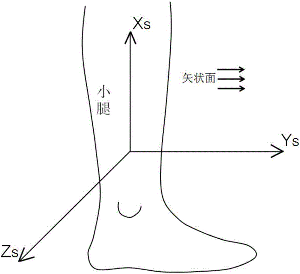
[0044] (1) Define the coordinate system of the measured object:

[0045] In this embodiment, the measured object is the calf, and the user defines the calf coordinate system as figure 1 Shown. Define the calf Z axis perpendicular to the sagittal plane (vertical to the horizontal plane and divide the human body into two parts, the main movement of the calf occurs in the sagittal plane when a person is walking), and define the calf X axis as the sagittal plane Th...


PUM


Abstract

The invention belongs to the field of sensors, and discloses a method for correcting the deviation of a coordinate axis of an inertial sensor. The method is mainly used for eliminating a sampling error caused by the deviation of the coordinate axis due to the wrong placement position of the inertial sensor which is placed on an objected to be measured. The method is simple, convenient and fast to use; the method does not need other devices, thus being low in cost; the method can be used for carrying out high-precision correction on the deviation of the coordinate axis of the inertial sensor.

Description

Technical field [0001] The invention belongs to the field of sensors, and particularly relates to a method for correcting the offset of the coordinate axis of an inertial sensor. Background technique [0002] Inertial sensors are sensors that detect and measure acceleration, tilt, shock, vibration, rotation, and motion with multiple degrees of freedom. Inertial sensors include accelerometers and angular velocity sensors (gyros) and their single, dual, and three-axis combinations. Most of the inertial sensors on the market now integrate three-axis accelerometers and three-axis gyroscopes. They are usually small, cheap, and easy to use, so they are widely used in data measurement, especially in the aerospace and wearable devices. Through the inertial sensor, the acceleration, angular velocity and attitude of the object can be measured. [0003] However, because the inertial sensor is small and exquisite, the coordinate axis is often offset during the manufacturing and welding proces...

Claims


Application Information

Patent Timeline
IPC IPC(8): G01C25/00
CPCG01C25/005
Inventor 刘涛王磊李庆国
Owner ZHEJIANG UNIV
Why Eureka
Try Eureka