Special equipment for detecting object surface normal errors on basis of image reflection method

A technology of object surface and reflection image, applied in the field of optical detection, can solve the problems of cost and installation position influence, maximum angle difference, high cost, achieve high-precision optical detection, achieve multiple points, and low equipment cost.

Active Publication Date: 2017-05-31
大连鉴影光学科技有限公司
View PDF9 Cites 1 Cited by
  • Summary
  • Abstract
  • Description
  • Claims
  • Application Information

AI Technical Summary

Problems solved by technology

However, laser reflective detection has its disadvantages: (1) the cost is high, and the cost of a single instrument is thousands of yuan; (2) affected by the cost and installation location, it is impossible to detect more points, usually only dozens of points can be detected , it is impossible to get more surface normal conditions
Compared with laser detection, three-dimensional scanning can achieve more point measurement, but this device also has obvious disadvantages: the scanned three-dimensional surface is composed of point cloud ima

Method used


Image

  • Special equipment for detecting object surface normal errors on basis of image reflection method
  • Special equipment for detecting object surface normal errors on basis of image reflection method
  • Special equipment for detecting object surface normal errors on basis of image reflection method

Examples


Embodiment Construction

[0017] In order to make the technical problems solved by the present invention, the technical solutions adopted and the technical effects achieved clearer, the present invention will be further described in detail below in conjunction with the accompanying drawings and embodiments. It should be understood that the specific embodiments described here are only used to explain the present invention, but not to limit the present invention. In addition, it should be noted that, for the convenience of description, only parts related to the present invention are shown in the drawings but not all content.

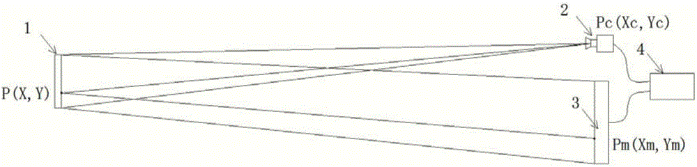
[0018] Please refer to figure 1 In this embodiment, the image acquisition device 2 and the image display device 3 are placed in front of the measured object 1; the industrial computer 4 and the image acquisition device 2 can be connected in a wired USB, Gige, Camera link or wireless manner, and the image display device Use HDMI, VGA, DSI and other interfaces to connect.

[0019] ...


PUM


Abstract

The invention discloses special equipment for detecting object surface normal errors on the basis of an image reflection method. Image collecting equipment and image display equipment are placed in front of a tested object; an industrial personal computer is connected with the image collecting equipment through wired USB, Gige and Camera link or connected wirelessly, and is connected with the image display equipment through an HDMI (high-definition multimedia interface), a VGA (video graphics array) interface and a DSI (display serial interface); the image collecting equipment is arranged right in front of the tested object, and a lens faces a to-be-tested part and used for collecting shot images of the tested object; the image display equipment is arranged in the position having the same distance with the lower side of the front end of the tested object and the image collecting equipment, and a connecting line of the centers of the image collecting equipment and the tested object and a connecting line of centers of the tested object and the image display equipment are symmetric to a center normal of the tested object.

Description

technical field [0001] The invention relates to the technical field of optical detection, in particular to a special device for detecting the surface normal error of an object based on a reflection image method. Background technique [0002] In the field of surface profile measurement of optical objects, the surface normal, as a direct factor affecting light reflection, usually needs to focus on detection. For example, in the detection of micro-arc curved mirrors in the solar thermal field, its surface normal directly affects the light-gathering effect, reduces the use efficiency of the product, and affects the stability of the product, thereby affecting the use of the product. [0003] There are two main detection methods currently used, namely laser detection and three-dimensional scanning, and the equipment used are: laser reflection detection equipment and three-dimensional scanning detection equipment. [0004] Laser reflection detection equipment adopts the method of ...

Claims


Application Information

Patent Timeline
IPC IPC(8): G01M11/02
CPCG01M11/0257
Inventor 郭右利付瑶
Owner 大连鉴影光学科技有限公司
Why Eureka
Try Eureka