Verification method and experimental device for grid impedance recognition

A technology of grid impedance and voltage source type, applied in the direction of measuring resistance/reactance/impedance, measuring devices, measuring electricity, etc., can solve the difficulty of determining the accuracy of the grid impedance identification method, grid interference, and the complexity of the verification process of the grid impedance identification method and other problems, to achieve the effect of simplifying the extraction process, reducing calculation pressure, and improving security

Active Publication Date: 2017-05-31
HEFEI UNIV OF TECH
View PDF3 Cites 26 Cited by
  • Summary
  • Abstract
  • Description
  • Claims
  • Application Information

AI Technical Summary

Benefits of technology

This patented technology helps prevent interference from electrical devices connected through an electricity network without affecting its quality or function properly. It does this by reducing noise caused during testing while still accurately identifying any changes that may occur over time. Overall, these technical improvements improve the efficiency and reliability of detecting abnormal voltages and currents in power grids.

Problems solved by technology

This technical problem addressed in this patents relates to improperly identifying the presence of low resistance ground fault currents caused by unpredictional sources such as stray voltages present during installation of gridders used in solar energy systems. Current solutions require expensive hardware tools like oscilloscope measurements and complex calculations processes.

Method used


Image

  • Verification method and experimental device for grid impedance recognition
  • Verification method and experimental device for grid impedance recognition
  • Verification method and experimental device for grid impedance recognition

Examples


Embodiment Construction

[0046] The preferred modes of the present invention will be further described in detail below in conjunction with the accompanying drawings.

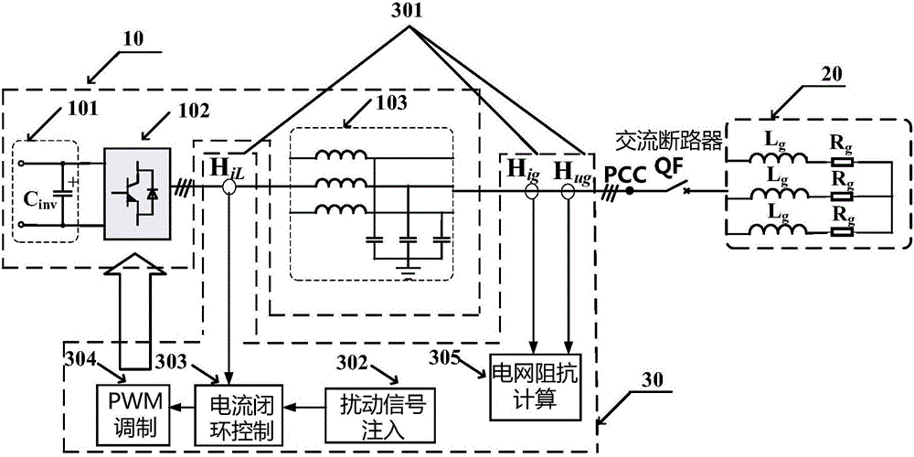
[0047] figure 1 The structural diagram of the experimental device for verifying the grid impedance identification method, as can be seen from the figure, the experimental device structure includes a voltage source inverter 10 , a grid impedance 20 and a grid impedance identification unit 30 .

[0048] The voltage source inverter 10 includes a DC side 101, a three-phase full-bridge inverter circuit 102 and an LC filter 103, and the filter capacitor C of the DC side 101 inv The output end of the three-phase full-bridge inverter circuit 102 is connected to the input end, and the output end of the three-phase full-bridge inverter circuit 102 is connected to the input end of the LC filter 103, and the output end of the LC filter 103 is connected to the grid impedance 20 is connected to the input terminal.

[0049] The grid impedance 20 is ...


PUM


Abstract

The invention provides a verification method and an experimental device for grid impedance recognition. The experimental device comprises a voltage source inverter (10), a grid impedance unit (20) and a grid impedance recognition unit (30). The specific operation process for verifying grid impedance recognition by the experimental device comprises the following steps: a disturbing signal injection unit (301) injects disturbing signals into an inverter control system, current response signals iga, igb and igc and voltage response signals uga, ugb and ugc of a PCC (point of common coupling) are acquired respectively by a current sensor Hig and a voltage sensor Hug on a grid-connected side, acquired signals are input into a grid impedance calculation unit (305), and grid impedance is obtained through calculation. A grid impedance recognition method can be verified accurately and reliably by the experimental device, and adverse effect on power quality is avoided.

Description


Claims


Application Information

Patent Timeline
Owner HEFEI UNIV OF TECH
Why Eureka
Try Eureka