Stereoscopic display device and method
A stereoscopic display device and technology of stereoscopic display, which are applied to optical elements, optics, instruments, etc., can solve the problems of affecting viewing effect, data errors, inconvenience for doctors to perform operations, etc., and achieve the effect of good stereoscopic display effect and accurate position information.
- Summary
- Abstract
- Description
- Claims
- Application Information
AI Technical Summary
Problems solved by technology
Method used
Image
Examples
Embodiment approach 1
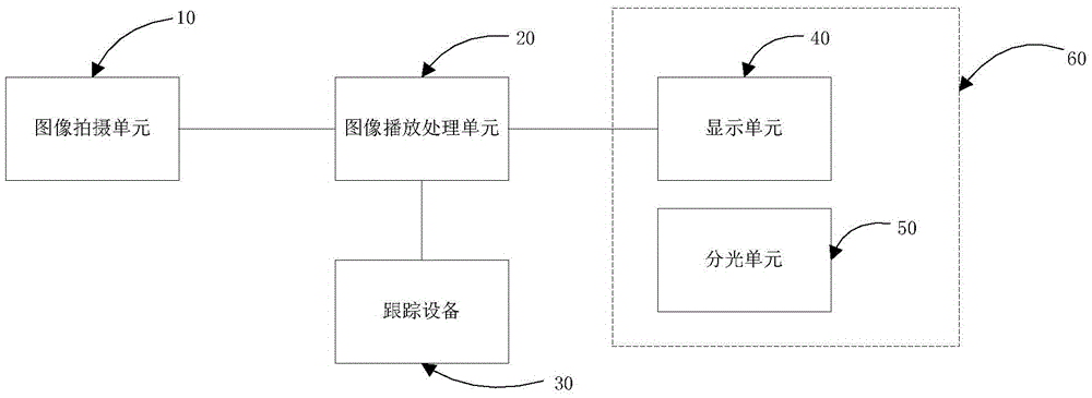
[0028] See figure 1 , figure 1 It is a schematic diagram of the structure of the stereoscopic display device of the present invention. Such as figure 1 As shown, the stereoscopic display device of the present invention includes a tracking device 30, a spectroscopic unit 50, and a display unit 40. The tracking device 30 is used to obtain position information of a target object, and the spectroscopic unit 50 is located on the display side of the display unit 40, The image displayed by the display unit 40 is spatially divided into a left view and a right view. The stereoscopic display device also includes an image playback processing unit 20, respectively connected to the tracking device 30 and the display unit 40. The image playback processing unit 20 is based on the position information of the target object, the grating parameters of the spectroscopic unit 50, and the display unit 40. The image to be played is processed in real time with the display parameters of, and then sent ...
Embodiment 1
[0037] In Embodiment 1 of the present invention, in order to obtain a better real-time stereoscopic display effect, it is necessary to perform an optical design on the spectroscopic unit and the display unit according to the grating parameters of the spectroscopic unit and the display parameters of the display unit. The optical design is based on the following formula:
[0038]
[0039]
[0040] (3) m*t=p-pitch
[0041] In the above formula, F is the distance between the light splitting unit and the display unit (that is, the distance between the grating in the above-mentioned grating parameter and the display panel), L is the distance between the viewer and the display unit,
[0042] IPD is the matching interpupillary distance, the distance between ordinary people’s pupils, for example, the general value is 62.5mm, l-pitch is the pitch of the light splitting unit, and p-pitch is the pixel arrangement on the display unit Pitch, n is the number of stereo views, m is the number of pixe...
Embodiment 2
[0049] See Figure 4 , Figure 4 It shows a schematic structural diagram of a preferred embodiment of the tracking device in the stereoscopic display device of the first embodiment of the present invention. Such as Figure 4 As shown, Embodiment 2 of the present invention also proposes another tracking device 30, which includes:
[0050] The marker point setting unit 1 is used to set more than three marker points corresponding to the spatial position of the target object; the marker points here can be set on the target object, or not on the target object, but set relative to the target object The position relationship is also available on objects that move synchronously with the target object. For example, if the target object is the human eye, you can set mark points around the orbit of the human eye; or arrange glasses around the human eye and set the mark point on the frame of the glasses, or set the mark point in the position relationship with the human eye On the ears of re...
PUM
 Abstract
Description
Claims
Application Information
 - R&D
- Intellectual Property
- Life Sciences
- Materials
- Tech Scout
- Unparalleled Data Quality
- Higher Quality Content
- 60% Fewer Hallucinations
Browse by: Latest US Patents, China's latest patents, Technical Efficacy Thesaurus, Application Domain, Technology Topic, Popular Technical Reports.
© 2025 PatSnap. All rights reserved.Legal|Privacy policy|Modern Slavery Act Transparency Statement|Sitemap|About US| Contact US: help@patsnap.com


