A long-wave infrared continuous zoom online fast compensation adjustment device and method
A long-wave infrared, adjusting device technology, applied in optical components, instruments, optics, etc., can solve problems such as defocusing, lens damage, etc., and achieve the effects of improving assembly and adjustment efficiency, avoiding lens damage, and reducing assembly and adjustment costs.
- Summary
- Abstract
- Description
- Claims
- Application Information
AI Technical Summary
Problems solved by technology
Method used
Image
Examples
Embodiment 1
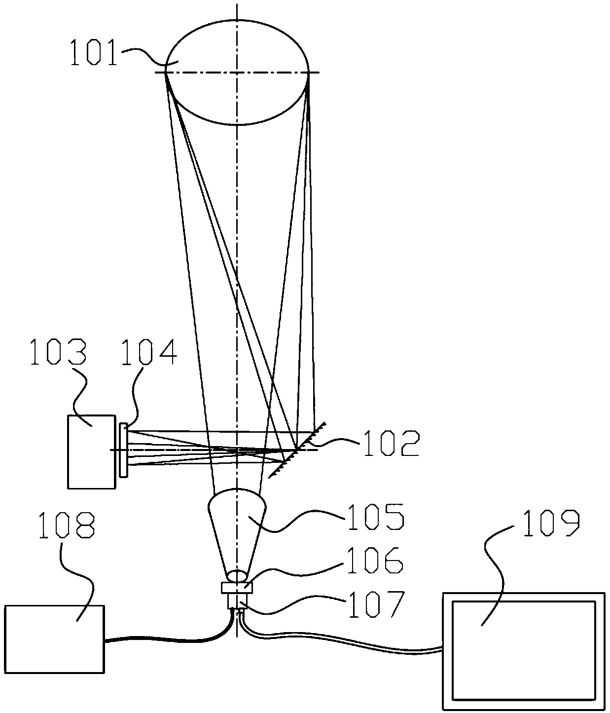
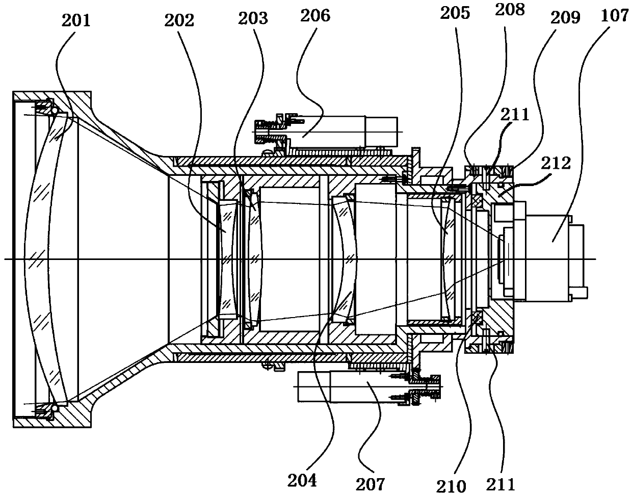
[0035] Such as figure 1 As shown, the supplementary device includes a reflective infrared collimator 101, a mirror 102, a black body 103, a target 104, a long-wave infrared continuous zoom lens 105, an adjustment device 106, a detector 107, a control circuit 108 and a display 109, wherein, The long-wave infrared continuous zoom lens 105 is located at the rear of the reflective infrared collimator 101, the adjustment device 106 is connected behind the long-wave infrared continuous zoom lens 105, the detector 107 is connected at the rear of the adjustment device 106, and the mirror 102 is located at the right of the infrared lens 105. In the front, the target 104 is located at the left front of the infrared lens, and the black body 103 is located behind the target 104. The control circuit 108 is used to drive the zoom / focus action and read and record the position information of each focal length. The display 109 is used to observe the infrared lens and the detector in real time. ...
Embodiment 2
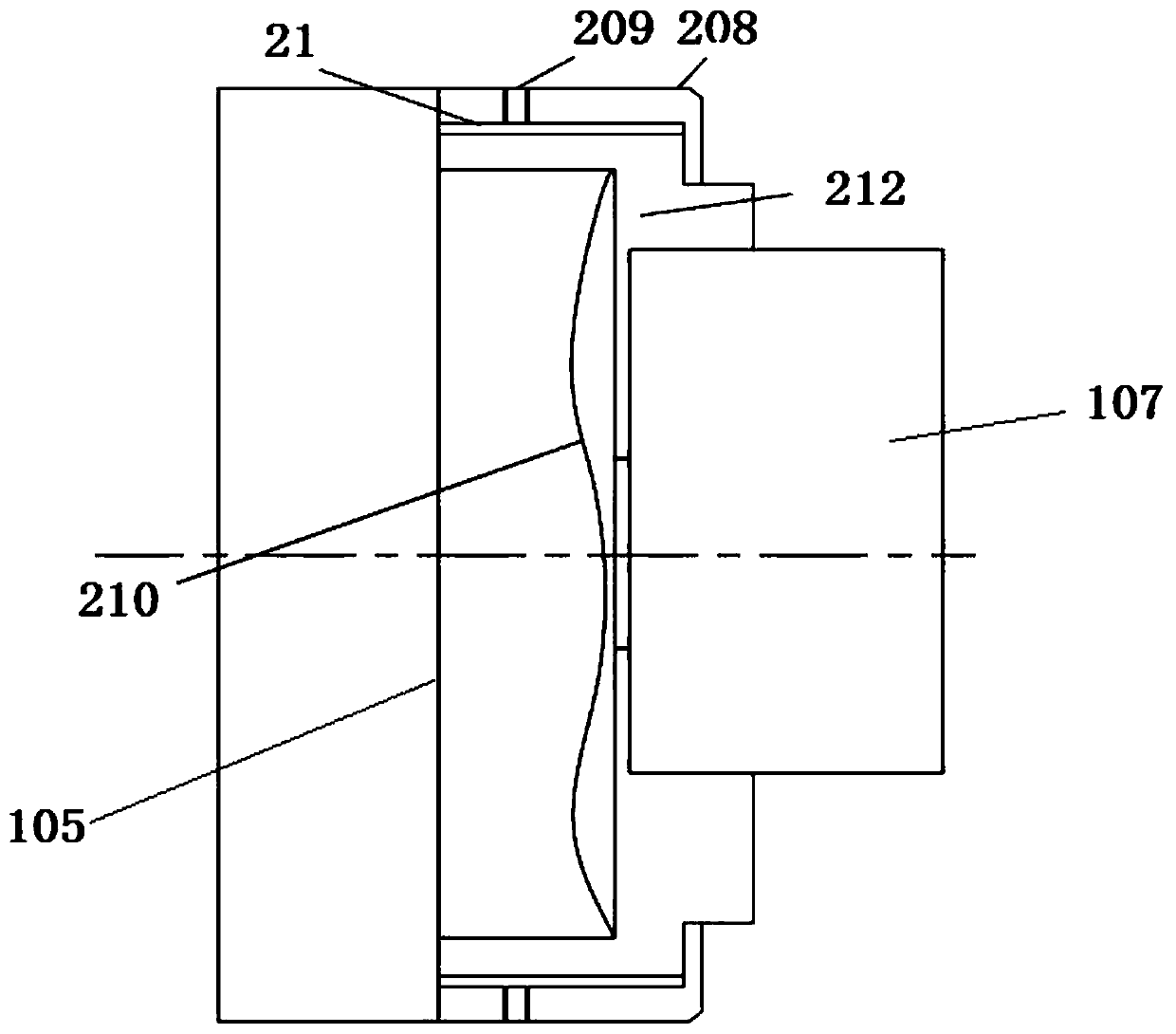
[0044] See image 3 , The displacement adjustment mechanism 21 is a screw thread, and there is a screw thread on the adjustment inner cylinder 212, which cooperates with the screw thread on the adjustment handwheel 208 to drive the detector 107 to move forward / backward along the optical axis.
[0045] The end of the infrared continuous zoom lens 105 is provided with a radial groove, and there is a screw hole on the adjustment handwheel 208, which is connected with the infrared continuous zoom lens 105 by a screw. move in.
Embodiment 3
[0047] See image 3 , the displacement adjustment mechanism 21 is a spiral groove, and the spiral groove on the adjustment inner cylinder 212 cooperates with the spiral groove on the adjustment hand wheel 208 to drive the detector 107 to move forward / backward along the optical axis.
[0048] The end of the infrared continuous zoom lens 105 is provided with a radial groove, and there is a screw hole on the adjustment handwheel 208, which is connected with the infrared continuous zoom lens 105 by a screw. move in.
PUM
 Abstract
Description
Claims
Application Information
 - R&D
- Intellectual Property
- Life Sciences
- Materials
- Tech Scout
- Unparalleled Data Quality
- Higher Quality Content
- 60% Fewer Hallucinations
Browse by: Latest US Patents, China's latest patents, Technical Efficacy Thesaurus, Application Domain, Technology Topic, Popular Technical Reports.
© 2025 PatSnap. All rights reserved.Legal|Privacy policy|Modern Slavery Act Transparency Statement|Sitemap|About US| Contact US: help@patsnap.com


