Plastic-frame-free backlight module

A backlight module, frame technology, applied in optics, nonlinear optics, instruments, etc., can solve problems such as influence, and achieve the effect of reducing problems, stable structure, and reducing adhesion.

Pending Publication Date: 2017-05-31
SHENZHEN BAOMING TECH
View PDF0 Cites 0 Cited by
  • Summary
  • Abstract
  • Description
  • Claims
  • Application Information

AI Technical Summary

Problems solved by technology

[0004] The problem to be solved by the present invention is how to provide a stable, frameless backlight module combination structure, which can solve the instability caused by the existing bonding method, or the influence of the excessive bonding position on the quality

Method used


Image

  • Plastic-frame-free backlight module
  • Plastic-frame-free backlight module
  • Plastic-frame-free backlight module

Examples


Embodiment 1

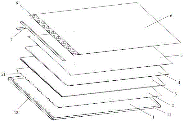
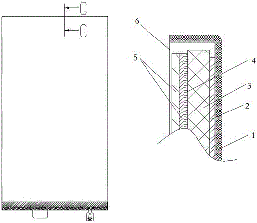
[0025] as attached figure 1 with attached figure 2 As shown, what this embodiment shows is a backlight module with three sides and no frame, and the specific structure is as follows:

[0026] On one side of the light bar 7 on the iron shell 1, a tooth-shaped protrusion 12 is provided. Firstly, a small hole is provided on the iron shell 1, and the iron shell 1 is placed in the injection mold, and the iron shell is directly placed on the iron shell through the injection mold. Serrated protrusions 12 are formed on the top of the body, because during the injection molding process, part of the molten colloid will enter the engaging holes, and after the overall colloid is cooled, the molten colloid remaining in the engaging holes will form the engaging protrusions , the protrusion can make the integral tooth-shaped protrusion 12 fixed on the iron shell, and the inner side of the iron shell frame 11 is coated with a reflective layer. One side of the light bar 7 of the reflector 2 ...

Embodiment 2

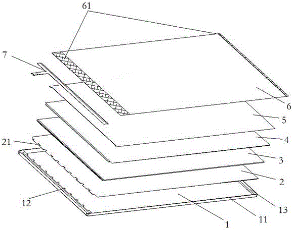
[0030] as attached figure 1 And attached figure 2 As shown, what this embodiment shows is a backlight module with no borders on both sides, and the specific structure is as follows:

[0031] One side of the light bar 7 on the iron shell 1 is provided with tooth-shaped protrusions 12, the inner side of the iron shell frame 11 is coated with an oil reflective layer, and an upper cushion frame 13 is arranged on the opposite side of the light bar 7 sides, and the tooth-shaped protrusions Both the riser 12 and the upper cushion frame 13 are formed by injection molding on the iron shell 1, specifically, the iron shell is placed on the injection mold, and the tooth-shaped protrusions 12 are directly formed on the iron shell through the injection mold, because in the injection molding process In the process, part of the molten colloid will enter into the engaging hole. After the whole colloid is cooled, the molten colloid remaining in the engaging hole will form an engaging protrusi...


PUM


Abstract

The invention discloses a plastic-frame-free backlight module which comprises an iron shell, a reflection piece, a light guide plate, a diffusion piece, a light intensifying piece and a lamp strip. An iron shell frame is arranged at the edge of the iron shell, the reflection piece is arranged in the iron shell, the light guide plate is arranged on the reflection piece, the diffusion piece is arranged on the light guide plate, the light intensifying piece is arranged on the diffusion piece, and the lamp strip is arranged on the reflection piece. The plastic-frame-free backlight module is characterized in that tooth-shaped protrusions are arranged on the iron shell, tooth-shaped notches are arranged on the reflection piece, and the tooth-shaped protrusions and the tooth-shaped notches can be mutually buckled. A plastic frame structure in an existing backlight module can be omitted, so that size of the frame is greatly reduced, a frame-free integral structure can be stably maintained, and the plastic-frame-free backlight module has excellent using effect.

Description

technical field [0001] The invention relates to the technical field of liquid crystal display, in particular to a backlight module without a plastic frame. Background technique [0002] At present, manufacturers of mobile terminals are pursuing display effects with narrow bezels or even bezel-less displays. Among them, the problem that needs to be solved most is how to deal with the frame in the backlight module. In mobile terminals with non-narrow bezels, the functional boards in the backlight module are usually pressed and confined in the plastic frame by using a plastic frame, and then the whole is put into an iron case and sealed with a light-shielding sheet. Combining in this way, the border is thicker because of the existence of the border of the plastic frame. [0003] In the existing technology, the frame is usually removed, the functional boards are bonded by gluing, and then fixed in the iron shell. This method is not only time-consuming and laborious, but also e...

Claims


Application Information

Patent Timeline
Patent Type & Authority Applications(China)
IPC IPC(8): G02F1/13357
CPCG02F1/133608G02F1/133603G02F1/133605
Inventor 岑科永丁清辉张春
Owner SHENZHEN BAOMING TECH
Why Eureka
Try Eureka