Backlight module and liquid crystal display

A technology of backlight module and light-emitting surface, which is applied in the direction of instruments, optics, nonlinear optics, etc., can solve the problems of unfavorable ultra-thin development trend, increase of LED module thickness, unfavorable LCD area dimming, etc., and achieve thinning Design, reduce distribution density, and realize the effect of regional dimming

Active Publication Date: 2017-05-31
TCL CHINA STAR OPTOELECTRONICS TECH CO LTD
View PDF15 Cites 14 Cited by
  • Summary
  • Abstract
  • Description
  • Claims
  • Application Information

AI Technical Summary

Problems solved by technology

This directly leads to an increase in the thickness of the LED module, which is not conducive to the current development trend of ultra-thin
[0005] If the distribution density of LED light sources on the PCB is reduced, that is, the distance between adjacent LED light sources is expanded to overcome the problem that the light between LED light sources is easy to cross and mix, which will lead to the problem of un

Method used


Image

  • Backlight module and liquid crystal display
  • Backlight module and liquid crystal display
  • Backlight module and liquid crystal display

Examples


Embodiment Construction

[0030] The content of the present invention will be described in detail below in conjunction with the accompanying drawings. The words "up", "down", "left" and "right" are all relative to the directions shown in the drawings and should not be construed as limiting the present invention.

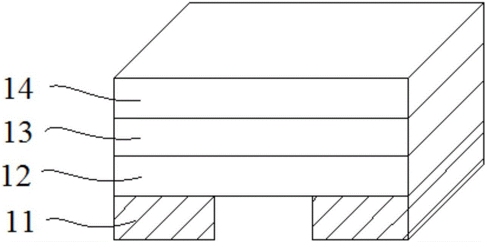
[0031] figure 1 It is a schematic diagram of the structure of the four-sided LED in the prior art. Usually, the four-sided LED is connected to the printed circuit board through the metal electrode 11, and the working mode of the four-sided LED is controlled through the printed circuit board.

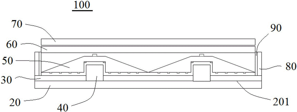
[0032] figure 2 It is a schematic structural diagram of the backlight module 100 proposed by the present invention, from figure 2It can be seen from the figure that the backlight module 100 includes a printed circuit board 20 , a first reflector 30 , an LED light source 40 , a light guide plate 50 , a diffusion plate 60 and an optical film 70 from bottom to top. The first reflection sheet 30 is arra...


PUM


Abstract

The invention relates to the field of liquid crystal display technologies. The backlight module provided by the invention sequentially comprises a printed circuit board, a first reflection plate, LED light sources, light guide plates, a diffusion plate and an optical diaphragm from the bottom up. Each light guide plate is of a rectangular structure with thin periphery and thick center, and is buckled on the corresponding LED light source via a groove at the center, and bumps are arranged on a first light reflection plane and a second light reflection plane of the light guide plate, so that mixing distance of light rays entering the light guide plate is increased, and thus the light rays are more uniformly distributed, generation of a dark space is avoided, and thin design of the liquid crystal display is facilitated; the LED light source and the light guide plate are on one-to-one correspondence, regional dimming is facilitated, and becomes more accurate during rectangular light emitting surfaces formed by the light guide plates; meanwhile, a use ratio of the light sources is further improved due to the arrangement of a third reflection plate. According to the liquid crystal display including the backlight module provided by the invention, regional dimming can be accurately achieved, and the thin design is also achieved.

Description

technical field [0001] The invention relates to the technical field of liquid crystal display, in particular to a backlight module and a liquid crystal display. Background technique [0002] At present, the penetration rate of LED as a backlight in the field of liquid crystal panel display has exceeded 90%. There are mainly two types of backlight module architectures: side-type and direct-type. The side-type LED backlight is to install the LED light source on the side of the light guide plate. Scattering directs the light out, the disadvantage of which is that the resulting picture contrast is relatively poor and local dimming is not possible. The direct-lit LED backlight can present images more accurately, and exhibit excellent color and light-dark contrast effects, which has gradually become the mainstream trend in the market. [0003] The direct type LED backlight module generally includes an LCD display screen, a diffuser plate and a PCB board. There are several packag...

Claims


Application Information

Patent Timeline
IPC IPC(8): G02F1/13357
CPCG02F1/133603G02F1/133605G02F1/133606G02F1/133607
Inventor 樊勇
Owner TCL CHINA STAR OPTOELECTRONICS TECH CO LTD
Why Eureka
Try Eureka