
Electronic equipment and control method thereof

An electronic device and touch technology, which is applied in the electronic field, can solve the problems of reduced strength and reliability, reduced user experience, and low reliability of electronic devices, so as to avoid false touches and improve user experience.

Inactive Publication Date: 2017-05-31
MEIZU TECH CO LTD
View PDF7 Cites 17 Cited by
  • Summary
  • Abstract
  • Description
  • Claims
  • Application Information

AI Technical Summary

Problems solved by technology

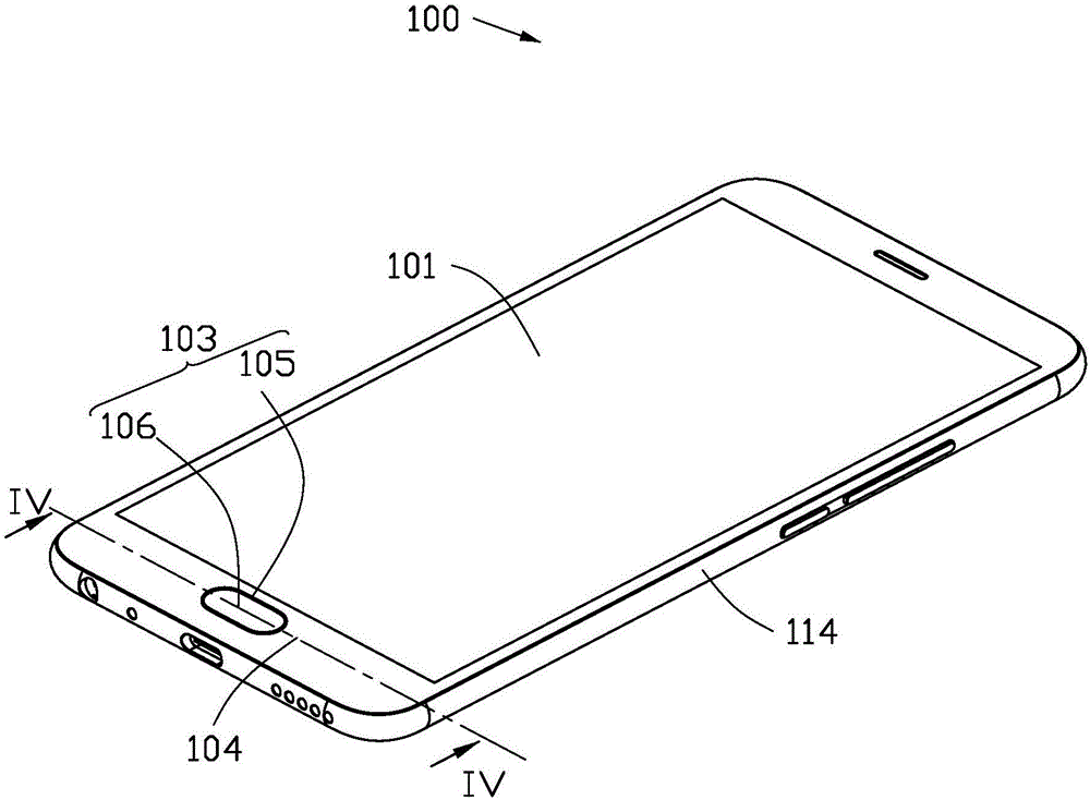
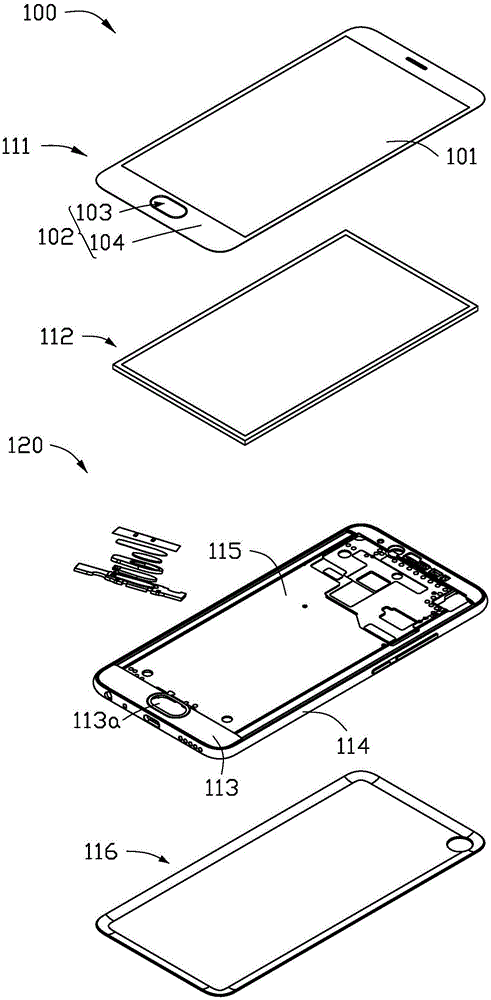
[0003] Generally, the existing biometric sensor is arranged on a specific key area (such as the home key area) of the cover plate of the electronic device, and the key area of ​​the cover plate has an opening, so that the biometric sensor The openings are exposed for user operation, and other openings or transmission areas (such as volume holes, camera areas, breathing light areas, distance sensor areas, etc.) may be provided on the cover of the electronic device, so that all There are too many elements in the area above the cover of the electronic device, and the structure is not simple, which affects the integrity of the electronic device and reduces the user experience
In addition, the manufacturing process of the cover plate is relatively complicated and the cost is high, especially the opening of the hole also leads to a decrease in the overall strength and reliability of the cover plate, and thus the reliability of the electronic device is low
In addition, in the existing electronic equipment, when the operating body accidentally touches the biometric sensor, the electronic equipment receives the false touch signal and controls the biometric sensor to turn on, which reduces the user experience.

Method used


Image

  • Electronic equipment and control method thereof
  • Electronic equipment and control method thereof
  • Electronic equipment and control method thereof

Examples


Embodiment Construction

[0027] The technical solutions in the embodiments of the present invention will be clearly and completely described below with reference to the accompanying drawings in the embodiments of the present invention. Obviously, the described embodiments are only a part of the embodiments of the present invention, but not all of the embodiments. Based on the embodiments of the present invention, all other embodiments obtained by those of ordinary skill in the art without creative efforts fall within the protection scope of the present invention.

[0028] It should be noted that the terms used in the embodiments of the present invention are only for the purpose of describing specific embodiments, and are not intended to limit the present invention. As used in this description and the appended claims, the singular forms "a," "the," and "the" are intended to include the plural forms as well, unless the context clearly dictates otherwise. It will also be understood that the term "and / or"...


PUM


Abstract

The invention provides electronic equipment and a control method thereof. The electronic equipment comprises a press key, a triggering sensor and a processor. The press key is used for detecting the triggering motion or biological information exerted on an operation body of the electronic equipment; the triggering sensor comprises a signal receiver, the signal receiver is used for receiving a first signal and converting the first signal into an electric signal, and the first signal is a visible light signal, an infrared light signal or an ultrasonic signal; the processor is used for receiving the electric signal, and judging whether the operation body operating the press key exist or not according to the electric signal, and when the operation body operates the press key, the processor controls the press key to open so as to detect the triggering motion or biological information exerted on the operation body of the electronic equipment. The electronic equipment is simple in design of cover plate, and high in reliability.

Description

technical field [0001] The present invention relates to the field of electronic technology, and in particular, to an electronic device and a control method thereof. Background technique [0002] With the development of information technology and electronic technology, electronic devices (such as mobile phones, tablets, etc.) have been closely related to people's daily life, because electronic devices can achieve various functions, such as making calls, taking pictures, and storing various files. , instant messaging, online payment, etc., people rely more and more on terminals, and all kinds of private information are stored on electronic devices, which makes the security of electronic devices particularly important. In the prior art, a biometric sensor (such as a fingerprint sensor, a heart rate sensor, etc.) is installed in an electronic device, and the biometric sensor can be used to identify the user's biometrics, so as to ensure the security or increase the use of the el...

Claims


Application Information

Patent Timeline
IPC IPC(8): G06F3/01G06F3/041
CPCG06F3/011G06F3/0416G06F2203/011
Inventor 李宁
Owner MEIZU TECH CO LTD
Learn More