
Switch contact temperature calculating method and switch contact temperature calculating device of solid insulated switch cabinet

A technology of solid insulated switches and switch contacts, which is applied in the field of power systems, can solve problems such as difficult implementation, unreliable temperature monitoring, and high cost, and achieve the effects of simple implementation, convenient calculation, and low cost

Active Publication Date: 2017-05-31
GUANGDONG UNIV OF TECH
View PDF4 Cites 8 Cited by
  • Summary
  • Abstract
  • Description
  • Claims
  • Application Information

AI Technical Summary

Problems solved by technology

[0003] The purpose of the present invention is to provide a method and device for calculating the contact temperature of a solid insulated switchgear switch to solve the problems of difficult implementation, high cost and unreliable monitoring temperature in the existing real-time monitoring technology of switch contact temperature

Method used


Image

  • Switch contact temperature calculating method and switch contact temperature calculating device of solid insulated switch cabinet
  • Switch contact temperature calculating method and switch contact temperature calculating device of solid insulated switch cabinet
  • Switch contact temperature calculating method and switch contact temperature calculating device of solid insulated switch cabinet

Examples


Embodiment Construction

[0034] In order to enable those skilled in the art to better understand the solution of the present invention, the present invention will be further described in detail below in conjunction with the accompanying drawings and specific embodiments. Apparently, the described embodiments are only some of the embodiments of the present invention, but not all of them. Based on the embodiments of the present invention, all other embodiments obtained by persons of ordinary skill in the art without making creative efforts belong to the protection scope of the present invention.

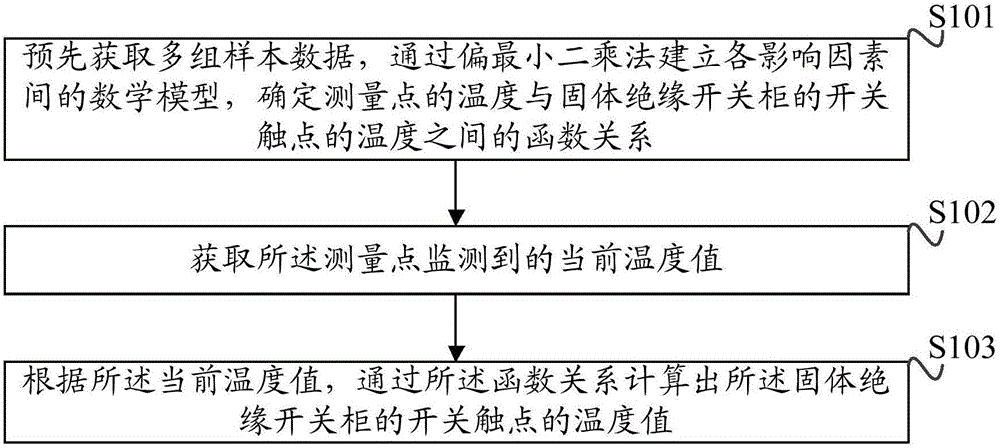
[0035] The flow chart of a specific embodiment of the method for calculating the temperature of the solid insulated switchgear switch contacts provided by the present invention is as follows: figure 1 As shown, the method includes:

[0036] Step S101: Obtain multiple sets of sample data in advance, establish a mathematical model among various influencing factors by partial least square method, and determine t...


PUM


Abstract

The invention discloses a switch contact temperature calculating method and a switch contact temperature calculating device of a solid insulated switch cabinet. The switch contact temperature calculating method comprises the following steps: establishing a mathematic model among respective influence factors based on a partial least squares method by means of acquiring a plurality of groups of sample data in advance, determining a function relationship between a temperature of a measured point and the temperature of a switch contact of the solid insulated switch cabinet, wherein the sample data comprises a plurality of groups of influence factor data capable of influence temperature variation of the switch contact, and the measured point is within a preset range at the periphery of the switch contact; acquiring the current temperature value monitored at the measured point; and calculating a temperature value of the switch contact of the solid insulated switch cabinet based on the function relationship according to the current temperature value. According to the switch contact temperature calculating method disclosed by the invention, temperature of a breaker contact is calculated dynamically by a partial least square based mathematic modeling method, without considering physical parameters of an externally wrapped insulating layer and a contact material, and therefore the calculation on the contact temperature is convenient. The switch contact temperature calculating method disclosed by the invention has the advantages of strong universality, easiness for implementation and low cost, and can provide reference for mastering operation status of the switch cabinet accurately in real time.

Description

technical field [0001] The invention relates to the technical field of power systems, in particular to a method and device for calculating the temperature of a switch contact of a solid insulation switch cabinet. Background technique [0002] The switchgear is an important equipment in the power system, and it is mainly responsible for the combined current of other electrical equipment and the grid. However, during the long-term operation of the switchgear, the contact resistance increases due to the aging of the contacts and poor contact. And power outages are not uncommon. Therefore, the online monitoring of the switch contact temperature of the switch cabinet is even more important. The current research on the contact temperature of the switchgear generally focuses on the development and improvement of temperature monitoring equipment. At present, there are mainly three operating techniques for real-time monitoring of the contact temperature. One method is to realize i...

Claims


Application Information

Patent Timeline
Patent Type & Authority Applications(China)
IPC IPC(8): G06F17/50
CPCG06F30/20
Inventor 聂一雄周文文徐卫东刁庆宪
Owner GUANGDONG UNIV OF TECH
Learn More